LMS1-SN PC Class Automatic Transfer Switch ATS Solenoid-type
LMS1-SN PC Class Automatic Transfer Switch ATS Solenoid-type
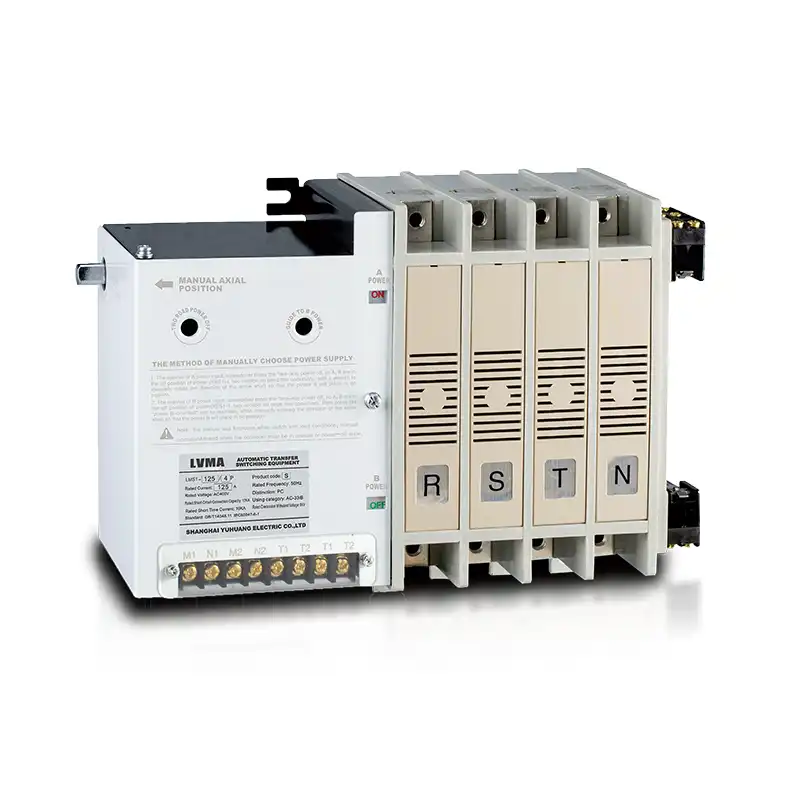
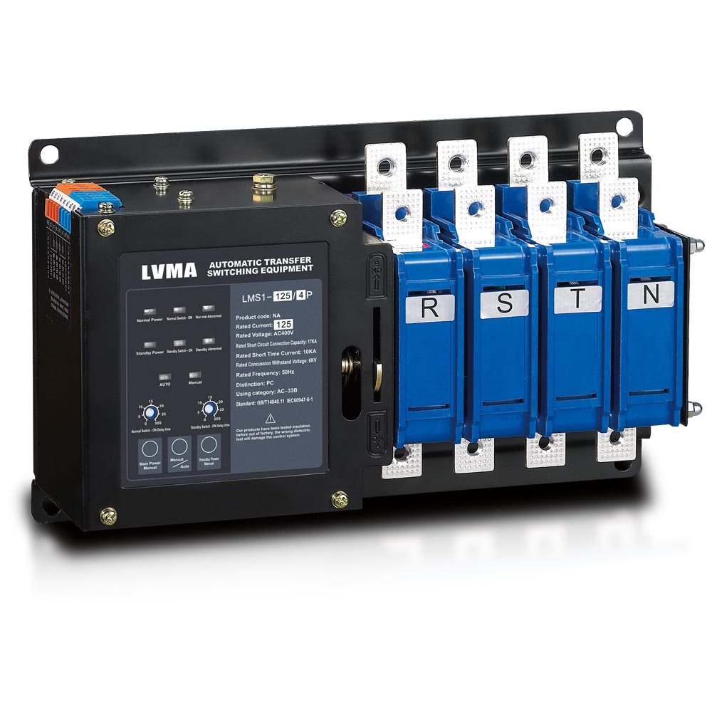
The LMS1-SN 4P Automatic Transfer Switch (ATS) is PC-class dual power changeover equipment rated at 4000A, 400V AC. Designed for automatic switching between mains utility power and backup generator supply, it combines auto-switch control with manual axial emergency operation. Featuring 4-pole configuration, high breaking capacity and flame retardant housing, this ATS is widely applied in commercial buildings, data centers, hospitals and industrial equipment for uninterrupted power supply.
The LMS1-SN 4P Automatic Transfer Switch (ATS) is PC-class dual power changeover equipment rated at 4000A, 400V AC. Designed for automatic switching between mains utility power and backup generator supply, it combines auto-switch control with manual axial emergency operation. Featuring 4-pole configuration, high breaking capacity and flame retardant housing, this ATS is widely applied in commercial buildings, data centers, hospitals and industrial equipment for uninterrupted power supply.
1. Product Overview
2.Key Features
- PC Class Safety Structure: Integral body isolation design, mechanical interlock prevents two power sources closing simultaneously, no short-circuit risk between dual power.
- Auto & Dual Manual Operation: Full automatic electronic control switching + axial manual rotary operation for emergency maintenance.
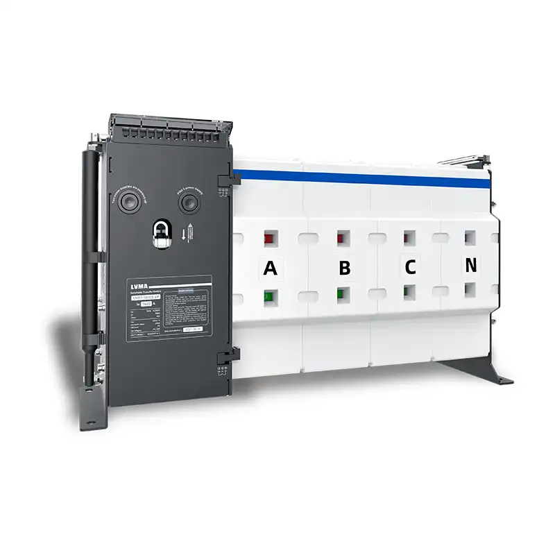
- 4P Four-Pole Design: Full isolation of R/S/T/N four lines, suitable for TN-S three-phase four-wire power distribution system.
- High Short-Circuit Withstand Capacity: Rated short-time withstand current up to 10kA, stable performance under grid short-circuit surge.
- Silver Alloy Contact: Low contact resistance, anti-welding, long service life under frequent switching operation.
- Wide Application Voltage: AC400V 50Hz standard rated voltage, compatible with global mainstream low-voltage distribution standard.
- Flame Retardant Enclosure: UL94-V0 fireproof plastic housing, anti-aging and high temperature resistant.
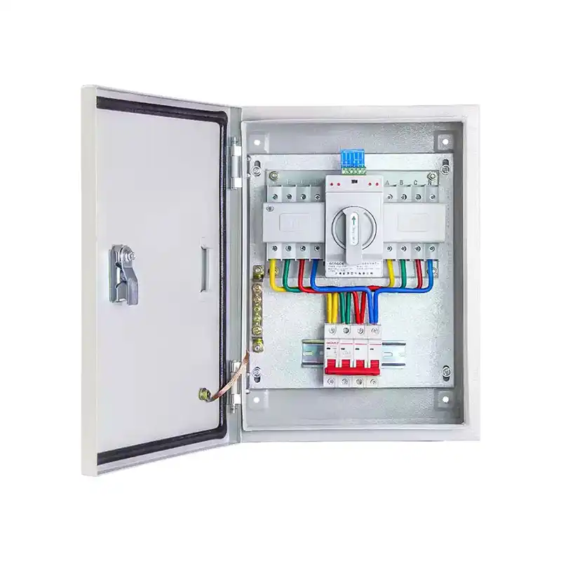
- Flexible Installation: Standard cabinet inner mounting design, matching most distribution box layout requirements.
- Drive mode: driven by electromagnetic coil, switching time 10–100 ms.
3. Technical Specification Table
| Item | Parameter |
|---|---|
| Model | LMS1-SN |
| Pole Number | 2P,3P.4P |
| Rated Current | 63~4000A |
| Rated Operational Voltage | AC400V,50Hz |
| Product Class | PC Class Automatic Transfer Switch |
| Short Time Withstand Current | 10kA |
| Control Mode | Automatic + Manual Axial Operation |
| Contact Material | Silver Alloy |
| Transfer Time | 10~100ms |
| Drive mode | Solenoid-type ATS |
| Compliance Standard | IEC60947-6-1, GB/T14048.11, CE Certified |
| Operating Temperature | -25℃ ~ +70℃ |
4. Working Principle
- Normal Main Power Supply: Primary grid power supplies load normally, ATS stays at A power ON position, standby source keeps standby state.
- Primary Power Abnormality: When main power loses phase, undervoltage or full power failure, control circuit detects fault signal and drives mechanism to switch load to B standby generator power automatically within preset delay time.
- Main Power Recovered: After main grid power restores to normal stable state, ATS automatically switches load back from standby source to primary power.
- Emergency Manual Mode: Cut off automatic control circuit, use axial rotary handle to manually toggle between A/B power for maintenance and equipment inspection.
5. Main Application Fields
- Critical infrastructure: Hospital power supply, data center & server room UPS front-end power switching
- Commercial real estate: Shopping mall, high-rise building fire control & elevator emergency power system
- Industrial field: Production line automation equipment, water pump & air compressor backup power
- Public facilities: Traffic control equipment, communication base station backup power distribution
6. Installation & Operation Guide
- Mounting: Fix ATS vertically inside distribution cabinet, reserve enough ventilation space around the device for heat dissipation.
- Wiring: Connect main grid source to A side terminals, standby generator power to B side terminals, load output to lower T1/T2 terminals; wire control signal to M1/N1/M2/N2 auxiliary terminal block.
- Automatic Debugging: Power on two sources sequentially, simulate main power cut-off test to verify automatic switching action normally.
- Manual Test: Disconnect control power, rotate axial manual handle to toggle between A/B position to confirm mechanical interlock works effectively.
- Safety Tip: Strictly forbid live-load manual switching without cutting off dual power supply per specification warning.
7. FAQ
Q1: What is PC class ATS vs CB class ATS?
Q2: Can this ATS work with diesel generator?
Q3: Is manual operation allowed under live load?
Q4: Does this ATS support custom version?
Q5: Is this product CE certified?
8. Technical Documents & Support
Download the full datasheet for detailed specifications, wiring diagrams, and trip coordination guidelines.
Contact our engineering team for custom configurations, communication module integration, or OEM solutions for large-scale projects.
Request a quote with your project details for bulk pricing, lead times, and compliance certifications.
1. Product Overview
2.Key Features
- PC Class Safety Structure: Integral body isolation design, mechanical interlock prevents two power sources closing simultaneously, no short-circuit risk between dual power.
- Auto & Dual Manual Operation: Full automatic electronic control switching + axial manual rotary operation for emergency maintenance.
- 4P Four-Pole Design: Full isolation of R/S/T/N four lines, suitable for TN-S three-phase four-wire power distribution system.
- High Short-Circuit Withstand Capacity: Rated short-time withstand current up to 10kA, stable performance under grid short-circuit surge.
- Silver Alloy Contact: Low contact resistance, anti-welding, long service life under frequent switching operation.
- Wide Application Voltage: AC400V 50Hz standard rated voltage, compatible with global mainstream low-voltage distribution standard.
- Flame Retardant Enclosure: UL94-V0 fireproof plastic housing, anti-aging and high temperature resistant.
- Flexible Installation: Standard cabinet inner mounting design, matching most distribution box layout requirements.
- Drive mode: driven by electromagnetic coil, switching time 10–100 ms.
3. Technical Specification Table
| Item | Parameter |
|---|---|
| Model | LMS1-SN |
| Pole Number | 2P,3P.4P |
| Rated Current | 63~4000A |
| Rated Operational Voltage | AC400V,50Hz |
| Product Class | PC Class Automatic Transfer Switch |
| Short Time Withstand Current | 10kA |
| Control Mode | Automatic + Manual Axial Operation |
| Contact Material | Silver Alloy |
| Transfer Time | 10~100ms |
| Drive mode | Solenoid-type ATS |
| Compliance Standard | IEC60947-6-1, GB/T14048.11, CE Certified |
| Operating Temperature | -25℃ ~ +70℃ |
4. Working Principle
- Normal Main Power Supply: Primary grid power supplies load normally, ATS stays at A power ON position, standby source keeps standby state.
- Primary Power Abnormality: When main power loses phase, undervoltage or full power failure, control circuit detects fault signal and drives mechanism to switch load to B standby generator power automatically within preset delay time.
- Main Power Recovered: After main grid power restores to normal stable state, ATS automatically switches load back from standby source to primary power.
- Emergency Manual Mode: Cut off automatic control circuit, use axial rotary handle to manually toggle between A/B power for maintenance and equipment inspection.
5. Main Application Fields
- Critical infrastructure: Hospital power supply, data center & server room UPS front-end power switching
- Commercial real estate: Shopping mall, high-rise building fire control & elevator emergency power system
- Industrial field: Production line automation equipment, water pump & air compressor backup power
- Public facilities: Traffic control equipment, communication base station backup power distribution
6. Installation & Operation Guide
- Mounting: Fix ATS vertically inside distribution cabinet, reserve enough ventilation space around the device for heat dissipation.
- Wiring: Connect main grid source to A side terminals, standby generator power to B side terminals, load output to lower T1/T2 terminals; wire control signal to M1/N1/M2/N2 auxiliary terminal block.
- Automatic Debugging: Power on two sources sequentially, simulate main power cut-off test to verify automatic switching action normally.
- Manual Test: Disconnect control power, rotate axial manual handle to toggle between A/B position to confirm mechanical interlock works effectively.
- Safety Tip: Strictly forbid live-load manual switching without cutting off dual power supply per specification warning.
7. FAQ
Q1: What is PC class ATS vs CB class ATS?
Q2: Can this ATS work with diesel generator?
Q3: Is manual operation allowed under live load?
Q4: Does this ATS support custom version?
Q5: Is this product CE certified?
8. Technical Documents & Support
Download the full datasheet for detailed specifications, wiring diagrams, and trip coordination guidelines.
Contact our engineering team for custom configurations, communication module integration, or OEM solutions for large-scale projects.
Request a quote with your project details for bulk pricing, lead times, and compliance certifications.

Related Products

Contact Us
Have questions about our products or services? Our team is here to help you with any inquiries.