

CJ19 Series Capacitor Switching AC Contactor, 25A-115A
CJ19 Series Capacitor Switching AC Contactor, 25A-115A
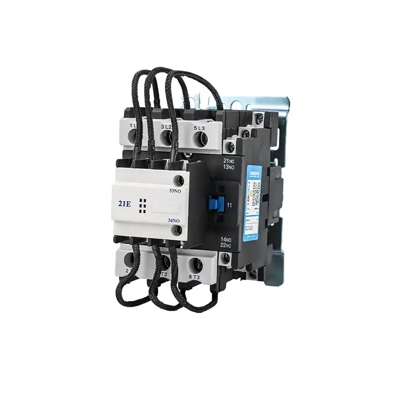
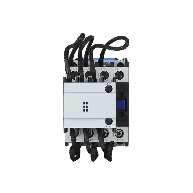
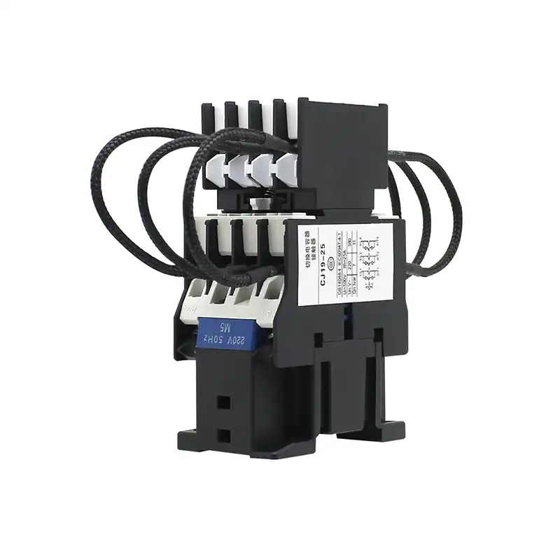
The CJ19 Series Capacitor Switching Contactor is a specialized AC contactor designed for power factor correction (PFC) capacitor banks. Available in ratings from 25A to 115A (CJ19-25, CJ19-32, CJ19-43, CJ19-63, CJ19-95, CJ19-115), these contactors include built-in pre-charge resistors to limit inrush current during capacitor switching. With silver alloy contacts, pure copper coils, and flame-retardant housings, they are ideal for industrial power distribution panels, reactive power compensation systems, and low-voltage capacitor bank applications.
The CJ19 Series Capacitor Switching Contactor is a specialized AC contactor designed for power factor correction (PFC) capacitor banks. Available in ratings from 25A to 115A (CJ19-25, CJ19-32, CJ19-43, CJ19-63, CJ19-95, CJ19-115), these contactors include built-in pre-charge resistors to limit inrush current during capacitor switching. With silver alloy contacts, pure copper coils, and flame-retardant housings, they are ideal for industrial power distribution panels, reactive power compensation systems, and low-voltage capacitor bank applications.
1. Product Overview
2. Key Features
- Capacitor Duty Design: Specialized for power factor correction capacitor switching, with built-in pre-charge resistors to limit inrush current.
- Wide Current Range: Available in 25A, 32A, 43A, 63A, 95A, and 115A ratings to suit different capacitor bank sizes.
- Pre-Charge Resistors: Integrated resistors limit initial inrush current, protecting contacts from damage during capacitor switching.
- Pure Copper Coils: High-efficiency coils ensure reliable operation and low power consumption.
- Silver Alloy Contacts: Low-resistance contacts minimize heating and extend electrical life under high inrush conditions.
- Flame-Retardant Housing: Heat-resistant plastic body (UL94 V-0) for enhanced safety and durability.
- Multiple Coil Voltages: Compatible with 220V and 380V AC coil options to match common control system voltages.
- IEC Certified: Compliant with IEC 60947-4-1 standards for low-voltage contactors.
3. Technical Specifications (Key Models)
| Parameter | CJ19-25 | CJ19-32 | CJ19-43 | CJ19-63 | CJ19-95 | CJ19-115 |
|---|---|---|---|---|---|---|
| Rated Operational Current (Ie) | 25A | 32A | 43A | 63A | 95A | 115A |
| Rated Operational Voltage (Ue) | 400V AC | 400V AC | 400V AC | 400V AC | 400V AC | 400V AC |
| Coil Voltage Options | 220V / 380V AC | 220V / 380V AC | 220V / 380V AC | 220V / 380V AC | 220V / 380V AC | 220V / 380V AC |
| Built-in Pre-Charge Resistors | Yes | Yes | Yes | Yes | Yes | Yes |
| Contact Material | Silver alloy | Silver alloy | Silver alloy | Silver alloy | Silver alloy | Silver alloy |
| Mounting Type | DIN Rail / Screw | DIN Rail / Screw | DIN Rail / Screw | Screw | Screw | Screw |
| Compliance | IEC 60947-4-1 | IEC 60947-4-1 | IEC 60947-4-1 | IEC 60947-4-1 | IEC 60947-4-1 | IEC 60947-4-1 |
4. Working Principle
- Pre-Charge Phase: When energized, the built-in resistors first connect to the capacitor bank, limiting the initial inrush current to a safe level.
- Main Contact Closure: After a short delay, the main contacts close, bypassing the resistors and connecting the capacitor bank directly to the power supply.
- Capacitor Operation: The capacitor bank operates normally, providing reactive power compensation to the system.
- De-Energization: When de-energized, the main contacts open first, followed by the pre-charge contacts, preventing voltage spikes and arc damage.
5. Applications
- Power Factor Correction (PFC): Capacitor bank switching in industrial and commercial power distribution systems.
- Reactive Power Compensation: Improving power factor in manufacturing plants, office buildings, and data centers.
- Low-Voltage Distribution Panels: Integral components in automatic power factor correction panels.
- Industrial Facilities: Motors, pumps, compressors, and other inductive loads requiring power factor correction.
- Utility Compliance: Meeting utility requirements for reactive power control and reducing penalties.
6. Installation & Operation Instructions
- Mounting: Secure the contactor to a standard 35mm DIN rail or flat surface using the mounting holes, ensuring adequate ventilation.
- Wiring:
- Connect the main power terminals (L1/L2/L3) to the incoming power supply.
- Connect the load terminals (T1/T2/T3) to the capacitor bank.
- Connect the coil terminals to the specified control voltage (220V or 380V AC).
- Operation:
- Apply control voltage to the coil to energize the contactor. The pre-charge resistors will activate first, followed by the main contacts.
- Remove control voltage to de-energize the contactor.
- Safety Notes:
- Disconnect power before wiring or servicing the contactor.
- Ensure the capacitor bank is fully discharged before maintenance.
7. Frequently Asked Questions (FAQ)
Q1: What is the difference between a CJ19 capacitor contactor and a standard contactor?
Q2: How do I choose the right CJ19 model?
Q3: What do the pre-charge resistors do?
Q4: Can I use a standard contactor for capacitor switching?
Q5: What coil voltage should I choose?
Q6: Is the CJ19 series CE certified?
8. Technical Documents & Support
Download full datasheets including complete specs, wiring schematics and selection guides.
Reach out to our technical team for project-specific customization and OEM/ODM service.
Submit a project inquiry to receive bulk pricing, production lead times and relevant compliance certificates.
1. Product Overview
2. Key Features
- Capacitor Duty Design: Specialized for power factor correction capacitor switching, with built-in pre-charge resistors to limit inrush current.
- Wide Current Range: Available in 25A, 32A, 43A, 63A, 95A, and 115A ratings to suit different capacitor bank sizes.
- Pre-Charge Resistors: Integrated resistors limit initial inrush current, protecting contacts from damage during capacitor switching.
- Pure Copper Coils: High-efficiency coils ensure reliable operation and low power consumption.
- Silver Alloy Contacts: Low-resistance contacts minimize heating and extend electrical life under high inrush conditions.
- Flame-Retardant Housing: Heat-resistant plastic body (UL94 V-0) for enhanced safety and durability.
- Multiple Coil Voltages: Compatible with 220V and 380V AC coil options to match common control system voltages.
- IEC Certified: Compliant with IEC 60947-4-1 standards for low-voltage contactors.
3. Technical Specifications (Key Models)
| Parameter | CJ19-25 | CJ19-32 | CJ19-43 | CJ19-63 | CJ19-95 | CJ19-115 |
|---|---|---|---|---|---|---|
| Rated Operational Current (Ie) | 25A | 32A | 43A | 63A | 95A | 115A |
| Rated Operational Voltage (Ue) | 400V AC | 400V AC | 400V AC | 400V AC | 400V AC | 400V AC |
| Coil Voltage Options | 220V / 380V AC | 220V / 380V AC | 220V / 380V AC | 220V / 380V AC | 220V / 380V AC | 220V / 380V AC |
| Built-in Pre-Charge Resistors | Yes | Yes | Yes | Yes | Yes | Yes |
| Contact Material | Silver alloy | Silver alloy | Silver alloy | Silver alloy | Silver alloy | Silver alloy |
| Mounting Type | DIN Rail / Screw | DIN Rail / Screw | DIN Rail / Screw | Screw | Screw | Screw |
| Compliance | IEC 60947-4-1 | IEC 60947-4-1 | IEC 60947-4-1 | IEC 60947-4-1 | IEC 60947-4-1 | IEC 60947-4-1 |
4. Working Principle
- Pre-Charge Phase: When energized, the built-in resistors first connect to the capacitor bank, limiting the initial inrush current to a safe level.
- Main Contact Closure: After a short delay, the main contacts close, bypassing the resistors and connecting the capacitor bank directly to the power supply.
- Capacitor Operation: The capacitor bank operates normally, providing reactive power compensation to the system.
- De-Energization: When de-energized, the main contacts open first, followed by the pre-charge contacts, preventing voltage spikes and arc damage.
5. Applications
- Power Factor Correction (PFC): Capacitor bank switching in industrial and commercial power distribution systems.
- Reactive Power Compensation: Improving power factor in manufacturing plants, office buildings, and data centers.
- Low-Voltage Distribution Panels: Integral components in automatic power factor correction panels.
- Industrial Facilities: Motors, pumps, compressors, and other inductive loads requiring power factor correction.
- Utility Compliance: Meeting utility requirements for reactive power control and reducing penalties.
6. Installation & Operation Instructions
- Mounting: Secure the contactor to a standard 35mm DIN rail or flat surface using the mounting holes, ensuring adequate ventilation.
- Wiring:
- Connect the main power terminals (L1/L2/L3) to the incoming power supply.
- Connect the load terminals (T1/T2/T3) to the capacitor bank.
- Connect the coil terminals to the specified control voltage (220V or 380V AC).
- Operation:
- Apply control voltage to the coil to energize the contactor. The pre-charge resistors will activate first, followed by the main contacts.
- Remove control voltage to de-energize the contactor.
- Safety Notes:
- Disconnect power before wiring or servicing the contactor.
- Ensure the capacitor bank is fully discharged before maintenance.
7. Frequently Asked Questions (FAQ)
Q1: What is the difference between a CJ19 capacitor contactor and a standard contactor?
Q2: How do I choose the right CJ19 model?
Q3: What do the pre-charge resistors do?
Q4: Can I use a standard contactor for capacitor switching?
Q5: What coil voltage should I choose?
Q6: Is the CJ19 series CE certified?
8. Technical Documents & Support
Download full datasheets including complete specs, wiring schematics and selection guides.
Reach out to our technical team for project-specific customization and OEM/ODM service.
Submit a project inquiry to receive bulk pricing, production lead times and relevant compliance certificates.

Related Products
Contact Us
Have questions about our products or services? Our team is here to help you with any inquiries.