Low Voltage Current Transformer, 50/5A to 2000/5A Ratios, 0.5 Class
Low Voltage Current Transformer, 50/5A to 2000/5A Ratios, 0.5 Class
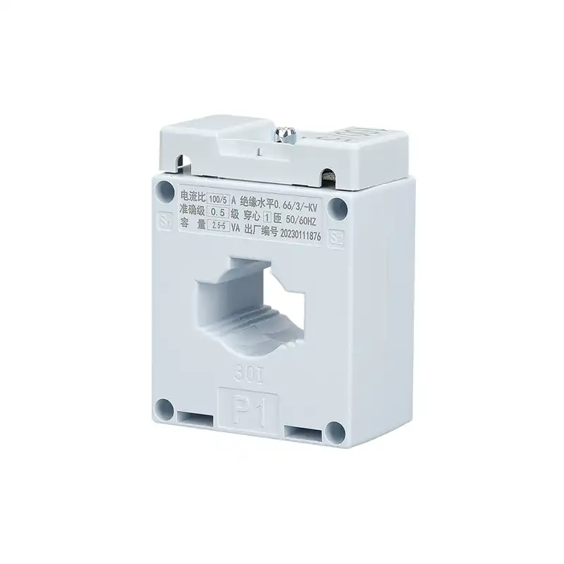
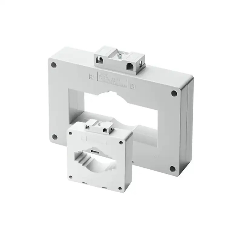
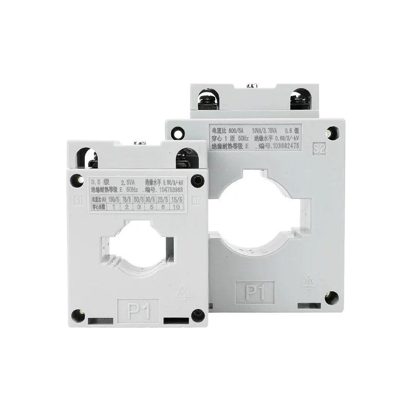
This low voltage current transformer (CT) series covers ratios from 50/5A up to 4000/5A, with 0.5 accuracy class and 2.5VA–30VA rated burden options. Designed for metering, measurement, and protection in power distribution systems, these through-type CTs step down high primary currents to a standard 5A secondary output. They feature flame-retardant housings and 3kV insulation, making them ideal for low-voltage panels, switchgear, and industrial control systems.
This low voltage current transformer (CT) series covers ratios from 50/5A up to 4000/5A, with 0.5 accuracy class and 2.5VA–30VA rated burden options. Designed for metering, measurement, and protection in power distribution systems, these through-type CTs step down high primary currents to a standard 5A secondary output. They feature flame-retardant housings and 3kV insulation, making them ideal for low-voltage panels, switchgear, and industrial control systems.
1. Product Overview
2. Key Features
- Wide Ratio Range: Available in 50/5A, 100/5A, 150/5A, 200/5A, 300/5A, 400/5A, 500/5A, 600/5A, 800/5A, 1000/5A, 1200/5A, 1500/5A, 2000/5A ratios to suit diverse applications.
- 0.5 Accuracy Class: Ensures precise measurement accuracy for billing and monitoring applications.
- Flexible Burden Options: Rated burdens from 2.5VA to 30VA, compatible with various meter and relay loads.
- 3kV Insulation Level: Provides high dielectric strength for enhanced safety in low-voltage systems.
- Flame-Retardant Housing: Durable plastic body ensures long-term performance in industrial environments.
- 50Hz Operation: Designed for standard 50Hz AC power systems.
- Through-Type Design: Simple installation by passing the primary conductor through the CT aperture.
3. Technical Specifications (Key Models)
| Ratio | Accuracy Class | Rated Burden | Frequency | Insulation Level |
|---|---|---|---|---|
| 50/5A | 0.5 | 2.5VA / 5VA | 50Hz | 3kV/1min |
| 100/5A | 0.5 | 2.5VA / 5VA / 10VA | 50Hz | 3kV/1min |
| 200/5A | 0.5 | 5VA / 10VA / 15VA | 50Hz | 3kV/1min |
| 300/5A | 0.5 | 5VA / 10VA / 15VA | 50Hz | 3kV/1min |
| 400/5A | 0.5 | 10VA / 15VA / 20VA | 50Hz | 3kV/1min |
| 500/5A | 0.5 | 10VA / 15VA / 20VA | 50Hz | 3kV/1min |
| 600/5A | 0.5 | 15VA / 20VA / 25VA | 50Hz | 3kV/1min |
| 800/5A | 0.5 | 15VA / 20VA / 25VA | 50Hz | 3kV/1min |
| 1000/5A | 0.5 | 20VA / 25VA / 30VA | 50Hz | 3kV/1min |
| 1500/5A | 0.5 | 20VA / 25VA / 30VA | 50Hz | 3kV/1min |
| 2000/5A | 0.5 | 20VA / 25VA / 30VA | 50Hz | 3kV/1min |
4. Working Principle
- Primary Conductor: The high-current primary conductor passes through the CT’s central aperture.
- Magnetic Induction: The primary current creates a magnetic field in the CT’s core, inducing a proportional current in the secondary winding.
- Secondary Output: The secondary winding delivers a reduced, standard 5A current, which is safe for measurement and protection devices.
- Isolation: The CT provides electrical isolation between the high-voltage primary circuit and low-voltage secondary instruments.
5. Applications
- Energy Metering: Accurate current measurement for billing and consumption monitoring (50/5A to 2000/5A ratios).
- Protection Relays: Providing proportional current signals for overcurrent and short-circuit protection.
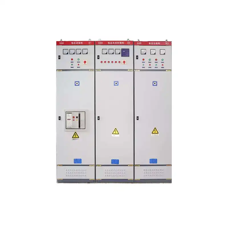
- Power Distribution Panels: Integration into low-voltage switchgear and distribution systems.
- Industrial Control Systems: Current monitoring for motors, generators, and industrial equipment.
- Building Automation: Power monitoring and load management in commercial and residential buildings.
6. Installation & Operation Instructions
- Mounting: Secure the CT in a suitable location within the distribution panel, ensuring the primary conductor passes through the central aperture.
- Wiring:
- Connect the primary conductor through the CT’s central hole (P1 direction).
- Connect the secondary terminals (S1/S2) to the meter or relay, ensuring correct polarity.
- Always short-circuit the secondary terminals when the CT is not connected to a load to prevent dangerous high voltages.
- Operation: The CT will continuously output a proportional 5A current based on the primary load current.
- Safety Notes:
- Never open-circuit the secondary winding of a current transformer under load.
- Ensure proper insulation and clearance to avoid electric shock hazards.
7. Frequently Asked Questions (FAQ)
Q1: What do the different ratios (50/5A, 2000/5A) mean?
Q2: What is 0.5 accuracy class?
Q3: How do I choose the right burden (2.5VA to 30VA)?
Q4: Can I open-circuit the secondary winding?
Q5: Are these CTs compatible with all 50Hz power systems?
8. Technical Documents & Support
Download the full datasheet for detailed specifications, wiring diagrams, and trip coordination guidelines.
Contact our engineering team for custom configurations, communication module integration, or OEM solutions for large-scale projects.
Request a quote with your project details for bulk pricing, lead times, and compliance certifications.
1. Product Overview
2. Key Features
- Wide Ratio Range: Available in 50/5A, 100/5A, 150/5A, 200/5A, 300/5A, 400/5A, 500/5A, 600/5A, 800/5A, 1000/5A, 1200/5A, 1500/5A, 2000/5A ratios to suit diverse applications.
- 0.5 Accuracy Class: Ensures precise measurement accuracy for billing and monitoring applications.
- Flexible Burden Options: Rated burdens from 2.5VA to 30VA, compatible with various meter and relay loads.
- 3kV Insulation Level: Provides high dielectric strength for enhanced safety in low-voltage systems.
- Flame-Retardant Housing: Durable plastic body ensures long-term performance in industrial environments.
- 50Hz Operation: Designed for standard 50Hz AC power systems.
- Through-Type Design: Simple installation by passing the primary conductor through the CT aperture.
3. Technical Specifications (Key Models)
| Ratio | Accuracy Class | Rated Burden | Frequency | Insulation Level |
|---|---|---|---|---|
| 50/5A | 0.5 | 2.5VA / 5VA | 50Hz | 3kV/1min |
| 100/5A | 0.5 | 2.5VA / 5VA / 10VA | 50Hz | 3kV/1min |
| 200/5A | 0.5 | 5VA / 10VA / 15VA | 50Hz | 3kV/1min |
| 300/5A | 0.5 | 5VA / 10VA / 15VA | 50Hz | 3kV/1min |
| 400/5A | 0.5 | 10VA / 15VA / 20VA | 50Hz | 3kV/1min |
| 500/5A | 0.5 | 10VA / 15VA / 20VA | 50Hz | 3kV/1min |
| 600/5A | 0.5 | 15VA / 20VA / 25VA | 50Hz | 3kV/1min |
| 800/5A | 0.5 | 15VA / 20VA / 25VA | 50Hz | 3kV/1min |
| 1000/5A | 0.5 | 20VA / 25VA / 30VA | 50Hz | 3kV/1min |
| 1500/5A | 0.5 | 20VA / 25VA / 30VA | 50Hz | 3kV/1min |
| 2000/5A | 0.5 | 20VA / 25VA / 30VA | 50Hz | 3kV/1min |
4. Working Principle
- Primary Conductor: The high-current primary conductor passes through the CT’s central aperture.
- Magnetic Induction: The primary current creates a magnetic field in the CT’s core, inducing a proportional current in the secondary winding.
- Secondary Output: The secondary winding delivers a reduced, standard 5A current, which is safe for measurement and protection devices.
- Isolation: The CT provides electrical isolation between the high-voltage primary circuit and low-voltage secondary instruments.
5. Applications
- Energy Metering: Accurate current measurement for billing and consumption monitoring (50/5A to 2000/5A ratios).
- Protection Relays: Providing proportional current signals for overcurrent and short-circuit protection.
- Power Distribution Panels: Integration into low-voltage switchgear and distribution systems.
- Industrial Control Systems: Current monitoring for motors, generators, and industrial equipment.
- Building Automation: Power monitoring and load management in commercial and residential buildings.
6. Installation & Operation Instructions
- Mounting: Secure the CT in a suitable location within the distribution panel, ensuring the primary conductor passes through the central aperture.
- Wiring:
- Connect the primary conductor through the CT’s central hole (P1 direction).
- Connect the secondary terminals (S1/S2) to the meter or relay, ensuring correct polarity.
- Always short-circuit the secondary terminals when the CT is not connected to a load to prevent dangerous high voltages.
- Operation: The CT will continuously output a proportional 5A current based on the primary load current.
- Safety Notes:
- Never open-circuit the secondary winding of a current transformer under load.
- Ensure proper insulation and clearance to avoid electric shock hazards.
7. Frequently Asked Questions (FAQ)
Q1: What do the different ratios (50/5A, 2000/5A) mean?
Q2: What is 0.5 accuracy class?
Q3: How do I choose the right burden (2.5VA to 30VA)?
Q4: Can I open-circuit the secondary winding?
Q5: Are these CTs compatible with all 50Hz power systems?
8. Technical Documents & Support
Download the full datasheet for detailed specifications, wiring diagrams, and trip coordination guidelines.
Contact our engineering team for custom configurations, communication module integration, or OEM solutions for large-scale projects.
Request a quote with your project details for bulk pricing, lead times, and compliance certifications.

Related Products
Contact Us
Have questions about our products or services? Our team is here to help you with any inquiries.