

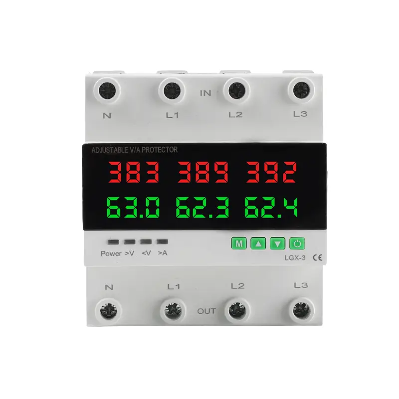
3 Phase Voltage Protector Over Under Voltage & Overcurrent Relay
3 Phase Voltage Protector Over Under Voltage & Overcurrent Relay
LMGQ8-63T is a DIN‑rail mounted 63A adjustable three‑phase four‑wire voltage & current protector. It features independent dual LED digital display to show real‑time voltage and current of L1, L2, L3 phases. This all‑in‑one relay provides comprehensive protection: over‑voltage, under‑voltage, adjustable over‑current, phase loss, wrong phase sequence, three‑phase voltage and current imbalance. All protection thresholds and delay timers are configurable. It supports auto reset after fault recovery, with manual lockout for repeated continuous over‑current faults, widely used for three‑phase motors, water pumps, generators and distribution cabinets.
LMGQ8-63T is a DIN‑rail mounted 63A adjustable three‑phase four‑wire voltage & current protector. It features independent dual LED digital display to show real‑time voltage and current of L1, L2, L3 phases. This all‑in‑one relay provides comprehensive protection: over‑voltage, under‑voltage, adjustable over‑current, phase loss, wrong phase sequence, three‑phase voltage and current imbalance. All protection thresholds and delay timers are configurable. It supports auto reset after fault recovery, with manual lockout for repeated continuous over‑current faults, widely used for three‑phase motors, water pumps, generators and distribution cabinets.
Product Overview
LMGQ8-63T is an intelligent DIN‑rail 35mm mount protective relay designed for AC 3‑phase 4‑wire (3P+N) power systems. It adopts high‑bright dual‑row digital LED screen: upper row displays real‑time phase voltage, lower row displays real‑time phase current for L1/L2/L3 separately.
Integrating multiple protection functions into one compact unit, LGX‑3 replaces several separate protection relays. It continuously monitors power quality, cuts off output rapidly once electrical faults are detected, and protects downstream three‑phase loads such as motors, water pumps, generator sets, photovoltaic distribution equipment and industrial machinery from burnout or reverse rotation damage. All protection parameters, trip delay and auto‑reset delay can be freely set via panel buttons.
Main Protection Functions
1. Over‑voltage & Under‑voltage Protection (P1 ~ P4, P6, P7)
- P1: Over‑voltage threshold; P2: Under‑voltage threshold
- P3: Over‑voltage action delay; P4: Under‑voltage action delay
- P6: Over‑voltage recovery hysteresis; P7: Under‑voltage recovery hysteresis The protector samples voltage of each phase continuously. When any phase voltage exceeds the over‑voltage setting or falls below under‑voltage setting and lasts longer than the set action delay, the relay trips and cuts load power, with
>Vor<Vindicator lit. Hysteresis prevents relay chattering around the threshold. Voltage must return to the safe hysteresis range before entering auto‑reset countdown.
2. Auto Reset / Start‑up Delay (P5)
P5 defines reset waiting time after fault condition clears. During countdown: screen flashes V/A data, fault indicator turns off, output stays disconnected. If a new fault occurs during countdown, reset will be aborted and output remains off. This stabilizes power supply for sensitive motors and avoids frequent on‑off cycling caused by grid fluctuations.
3. Phase‑Sequence Protection Enable / Disable (P8)
- ON (default): Wrong phase sequence triggers trip, screen shows fault code
L1‑L3‑L2, output locks off, no auto reset. User must correct wiring manually. Ideal for pumps and motors that cannot reverse. - OFF: Phase sequence detection disabled, suitable for loads insensitive to rotation direction.
4. Three‑Phase Voltage Imbalance Protection (P9, P10)
- P9: Voltage imbalance recovery value; P10: Voltage calibration offset When voltage difference between three phases exceeds the internal trip threshold, protection activates. The system will only allow auto reset after phase voltage difference drops below the P9 recovery value. P10 is used to calibrate display deviation so screen reading matches multimeter measurements.
5. Adjustable Over‑Current Protection (P11, P12)
- P11: Over‑current setting value (1A–63/80/100A)
- P12: Over‑current action delay (0.1s–10s) It monitors current of each phase independently. When load current exceeds the preset value and lasts beyond the action delay, the protector trips and the
>Aindicator lights. Short delay settings respond faster for short‑circuit risk; longer delay tolerates motor starting inrush current.
6. Three‑Phase Current Imbalance Protection (P13, P15)
- P13: Current imbalance threshold (OFF / 0.5A–10A)
- P15: Current calibration offset This function detects uneven current among three phases, which is an early warning signal of motor winding partial short‑circuit or mechanical blockage. Trip will activate when phase current difference exceeds the set value. P15 corrects sampling error for accurate current readings.
7. Continuous Over‑Current Lockout Protection (P14)
P14 sets the allowed count of repeated over‑current faults (OFF / 0–20 times). If over‑current faults occur repeatedly and reach the set count, LGX‑3 enters permanent lockout mode. Auto reset is disabled. Manual reset operation is required to restore output. This critical feature stops dangerous fault‑reset cycles that burn motors and wiring.
Display & Button Operation
Indicators:
Power: ON when output relay is closed and power feeds the load>V: Over‑voltage fault indicator<V: Under‑voltage fault indicator>A: Over‑voltage fault indicator
Buttons:
- M: Menu / Confirm button, enter parameter menu and save settings
- ▲ Up / ▼ Down: Increase or decrease parameter numbers
- Power key: Manual on/off switch for test and maintenance
Complete Parameter Menu Table (P1 ~ P15)
| Menu Code | Function | Setting Range | Factory Default |
|---|---|---|---|
| P1 | Over‑voltage protection threshold | 230‑300V | 260V |
| P2 | Under‑voltage protection threshold | 150‑220V | 180V |
| P3 | Over‑voltage action delay | 0.1‑10.0 s | 1.0s |
| P4 | Under‑voltage action delay | 0.1‑10.0 s | 1.0s |
| P5 | Reset / Start‑up delay | 5‑300 s | 30s |
| P6 | Over‑voltage recovery hysteresis | 2‑30V | 10V |
| P7 | Under‑voltage recovery hysteresis | 2‑30V | 10V |
| P8 | Phase‑sequence protection ON/OFF | ON / OFF | ON |
| P9 | Three‑phase voltage imbalance recovery value | 5V‑90V | 20V |
| P10 | Three‑phase voltage calibration | -9.5V ~ +9.5V | 0 |
| P11 | Over‑current protection value | 1A‑63/80/100A | 100A |
| P12 | Over‑current protection action time | 0.1s‑10s | 1s |
| P13 | Current imbalance value | OFF / 0.5A‑10A | OFF |
| P14 | Continuous over‑current protection frequency | OFF / 0‑20 | OFF |
| P15 | Three‑phase current error calibration | -9.5A ~ +9.5A | 0 |
Installation & Wiring Notes
- Mounting: Standard 35mm DIN rail for distribution cabinet
- Terminal marking:
IN= Power input (N, L1, L2, L3);OUT= Load output - Installation and parameter configuration must be completed by qualified electricians
- Rated current version: 63A (other ratings optional)
- Certificate: CE
Application Scenarios
Three‑phase asynchronous motors, water pump stations, generator output protection, construction temporary power boxes, farm irrigation control cabinets, commercial distribution panels, solar PV three‑phase output protection, air compressors and fan equipment.
Product Overview
LMGQ8-63T is an intelligent DIN‑rail 35mm mount protective relay designed for AC 3‑phase 4‑wire (3P+N) power systems. It adopts high‑bright dual‑row digital LED screen: upper row displays real‑time phase voltage, lower row displays real‑time phase current for L1/L2/L3 separately.
Integrating multiple protection functions into one compact unit, LGX‑3 replaces several separate protection relays. It continuously monitors power quality, cuts off output rapidly once electrical faults are detected, and protects downstream three‑phase loads such as motors, water pumps, generator sets, photovoltaic distribution equipment and industrial machinery from burnout or reverse rotation damage. All protection parameters, trip delay and auto‑reset delay can be freely set via panel buttons.
Main Protection Functions
1. Over‑voltage & Under‑voltage Protection (P1 ~ P4, P6, P7)
- P1: Over‑voltage threshold; P2: Under‑voltage threshold
- P3: Over‑voltage action delay; P4: Under‑voltage action delay
- P6: Over‑voltage recovery hysteresis; P7: Under‑voltage recovery hysteresis The protector samples voltage of each phase continuously. When any phase voltage exceeds the over‑voltage setting or falls below under‑voltage setting and lasts longer than the set action delay, the relay trips and cuts load power, with
>Vor<Vindicator lit. Hysteresis prevents relay chattering around the threshold. Voltage must return to the safe hysteresis range before entering auto‑reset countdown.
2. Auto Reset / Start‑up Delay (P5)
P5 defines reset waiting time after fault condition clears. During countdown: screen flashes V/A data, fault indicator turns off, output stays disconnected. If a new fault occurs during countdown, reset will be aborted and output remains off. This stabilizes power supply for sensitive motors and avoids frequent on‑off cycling caused by grid fluctuations.
3. Phase‑Sequence Protection Enable / Disable (P8)
- ON (default): Wrong phase sequence triggers trip, screen shows fault code
L1‑L3‑L2, output locks off, no auto reset. User must correct wiring manually. Ideal for pumps and motors that cannot reverse. - OFF: Phase sequence detection disabled, suitable for loads insensitive to rotation direction.
4. Three‑Phase Voltage Imbalance Protection (P9, P10)
- P9: Voltage imbalance recovery value; P10: Voltage calibration offset When voltage difference between three phases exceeds the internal trip threshold, protection activates. The system will only allow auto reset after phase voltage difference drops below the P9 recovery value. P10 is used to calibrate display deviation so screen reading matches multimeter measurements.
5. Adjustable Over‑Current Protection (P11, P12)
- P11: Over‑current setting value (1A–63/80/100A)
- P12: Over‑current action delay (0.1s–10s) It monitors current of each phase independently. When load current exceeds the preset value and lasts beyond the action delay, the protector trips and the
>Aindicator lights. Short delay settings respond faster for short‑circuit risk; longer delay tolerates motor starting inrush current.
6. Three‑Phase Current Imbalance Protection (P13, P15)
- P13: Current imbalance threshold (OFF / 0.5A–10A)
- P15: Current calibration offset This function detects uneven current among three phases, which is an early warning signal of motor winding partial short‑circuit or mechanical blockage. Trip will activate when phase current difference exceeds the set value. P15 corrects sampling error for accurate current readings.
7. Continuous Over‑Current Lockout Protection (P14)
P14 sets the allowed count of repeated over‑current faults (OFF / 0–20 times). If over‑current faults occur repeatedly and reach the set count, LGX‑3 enters permanent lockout mode. Auto reset is disabled. Manual reset operation is required to restore output. This critical feature stops dangerous fault‑reset cycles that burn motors and wiring.
Display & Button Operation
Indicators:
Power: ON when output relay is closed and power feeds the load>V: Over‑voltage fault indicator<V: Under‑voltage fault indicator>A: Over‑voltage fault indicator
Buttons:
- M: Menu / Confirm button, enter parameter menu and save settings
- ▲ Up / ▼ Down: Increase or decrease parameter numbers
- Power key: Manual on/off switch for test and maintenance
Complete Parameter Menu Table (P1 ~ P15)
| Menu Code | Function | Setting Range | Factory Default |
|---|---|---|---|
| P1 | Over‑voltage protection threshold | 230‑300V | 260V |
| P2 | Under‑voltage protection threshold | 150‑220V | 180V |
| P3 | Over‑voltage action delay | 0.1‑10.0 s | 1.0s |
| P4 | Under‑voltage action delay | 0.1‑10.0 s | 1.0s |
| P5 | Reset / Start‑up delay | 5‑300 s | 30s |
| P6 | Over‑voltage recovery hysteresis | 2‑30V | 10V |
| P7 | Under‑voltage recovery hysteresis | 2‑30V | 10V |
| P8 | Phase‑sequence protection ON/OFF | ON / OFF | ON |
| P9 | Three‑phase voltage imbalance recovery value | 5V‑90V | 20V |
| P10 | Three‑phase voltage calibration | -9.5V ~ +9.5V | 0 |
| P11 | Over‑current protection value | 1A‑63/80/100A | 100A |
| P12 | Over‑current protection action time | 0.1s‑10s | 1s |
| P13 | Current imbalance value | OFF / 0.5A‑10A | OFF |
| P14 | Continuous over‑current protection frequency | OFF / 0‑20 | OFF |
| P15 | Three‑phase current error calibration | -9.5A ~ +9.5A | 0 |
Installation & Wiring Notes
- Mounting: Standard 35mm DIN rail for distribution cabinet
- Terminal marking:
IN= Power input (N, L1, L2, L3);OUT= Load output - Installation and parameter configuration must be completed by qualified electricians
- Rated current version: 63A (other ratings optional)
- Certificate: CE
Application Scenarios
Three‑phase asynchronous motors, water pump stations, generator output protection, construction temporary power boxes, farm irrigation control cabinets, commercial distribution panels, solar PV three‑phase output protection, air compressors and fan equipment.

Related Products


Contact Us
Have questions about our products or services? Our team is here to help you with any inquiries.