

LVMA Project | Philippines 600A Customized Main Distribution Panel
The client is a local EPC contractor in the Philippines undertaking the construction of mid-rise commercial buildings in Metro Manila. Reliable power is needed to power the building. The project encountered several typical local power challenges during the planning phase:
Manila’s tropical climate brings consistently high humidity and sporadic outdoor rain splashes, and common thin-gauge electrical cabinets quickly rust, increasing the risk of short circuits and electric shock.
Local inspectors enforce strict Philippine Electrical Code (PEC) rules, including circuit isolation, mandatory shock warning signs, standardized wiring color coding, and dedicated grounding infrastructure. Mass-produced imitation cabinets have repeatedly failed municipal safety audits.
Frequent grid voltage fluctuations at urban construction sites in Metro Manila create overload risks; isolated branch circuit protection is needed to prevent a single circuit failure from causing an entire building to lose power
The contractor commissioned our factory to create a fully custom floor-standing distribution cabinet designed to address all of the above pain points and successfully pass official electrical inspections.
Customized cabinet design & hardware breakdown (with product photos)
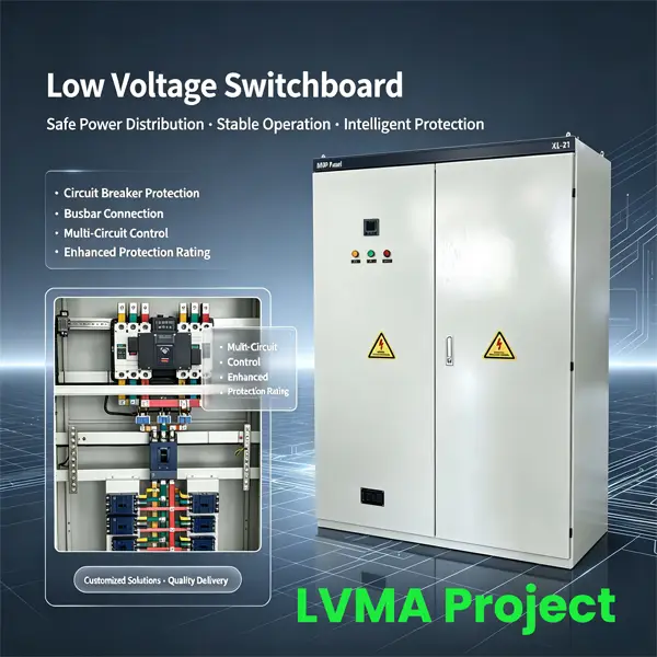
Exterior cabinet (second photo)
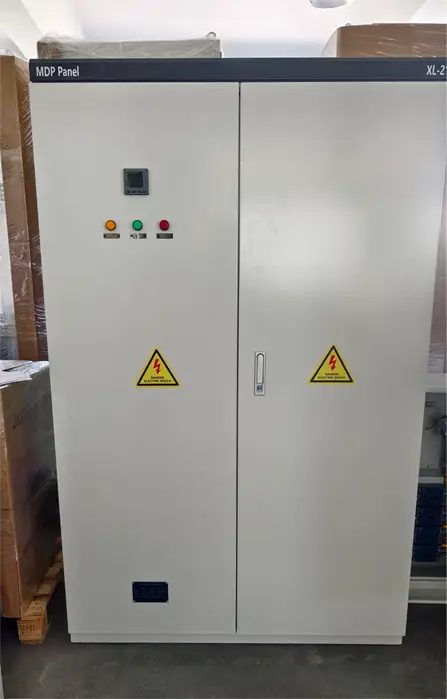
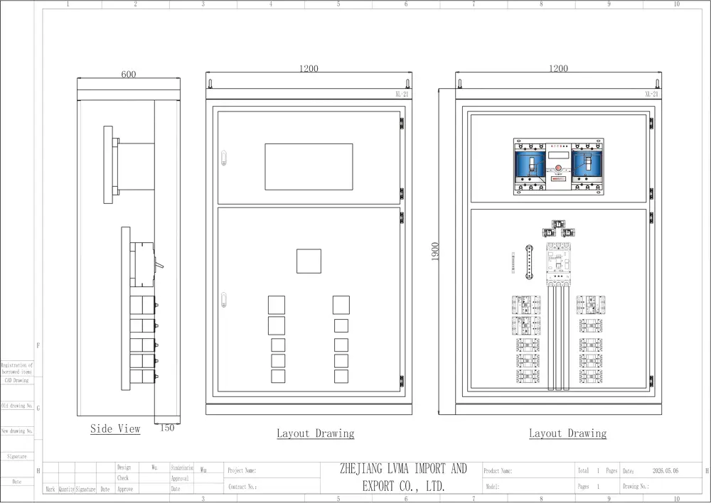
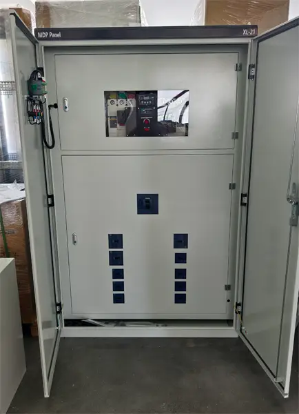
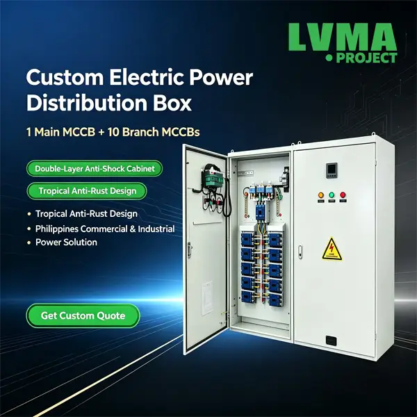
The shell is made of thick cold-rolled steel plate, anti-scratch and anti-rust powder coating, double-layer design, size 1200*1900*600, box thickness 1.5mm. The front panel integrates a digital multi-function power meter for real-time grid voltage, current and load monitoring. Three color-coded indicators provide intuitive status alerts: yellow indicates standby power status, green indicates normal operation, and red indicates circuit fault alarm. Standard yellow “Danger Electric Shock” warning sticker meets Philippine occupational safety labeling requirements and has lockable rotating handles on both sides to limit unauthorized access to the cabinet.
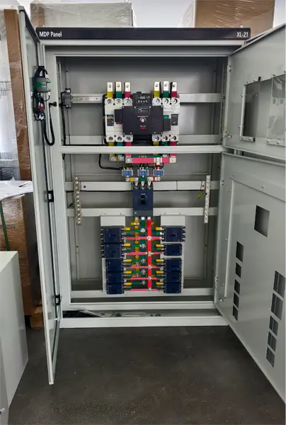
2. Tiered Internal Hardware Breakdown (Power flow sequence: incoming supply → outgoing feeders)
Top Tier: LMQ2CB-630/3P Automatic Transfer Switch (ATS)
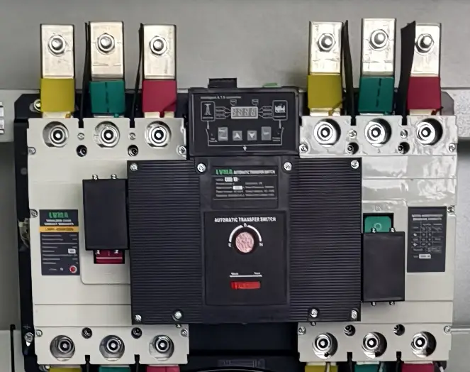
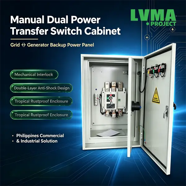
- Function: Interfaces with two independent utility feeds (normal supply + standby backup supply). It switches power to the backup feed automatically upon mains outage or abnormal voltage deviation to sustain power delivery for downstream critical loads, fitting premises with zero tolerance for blackouts such as production plants, server rooms and retail outlets. A manual rotary selector is integrated for forced source switching and full circuit isolation during maintenance work.
- Wiring standard: Three‑phase busbars follow industry color coding (yellow for Phase A, green for Phase B, red for Phase C, blue for neutral conductor). Tin plating on copper busbars mitigates resistive heat generation under high‑current operating conditions.
Middle Tier: Main Molded Case Circuit Breaker (MCCB)
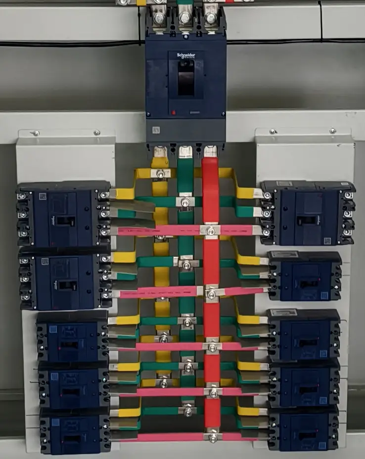
- Protection capabilities: Built‑in instantaneous short‑circuit tripping and time‑delayed overload tripping mechanisms cut off power supply to the whole cabinet promptly during short‑circuit faults or sustained overloading, stopping fault propagation across the distribution network. Auxiliary attachments including residual current and undervoltage trip coils can be fitted on demand.
Bottom Tier: Multiple Branch MCCBs
- Zoned power supply: Separate breakers serve workshop machinery, general lighting and dedicated power circuits. Tripping on one isolated branch will not interrupt power to other operational circuits, limiting outage scope and streamlining fault diagnostics.
- Coordinated selective tripping hierarchy: ATS (source switching) → main MCCB (system‑wide fault protection) → branch MCCBs (individual load safeguarding). This three‑tier scheme prevents unwanted upstream over‑tripping during localized circuit faults.
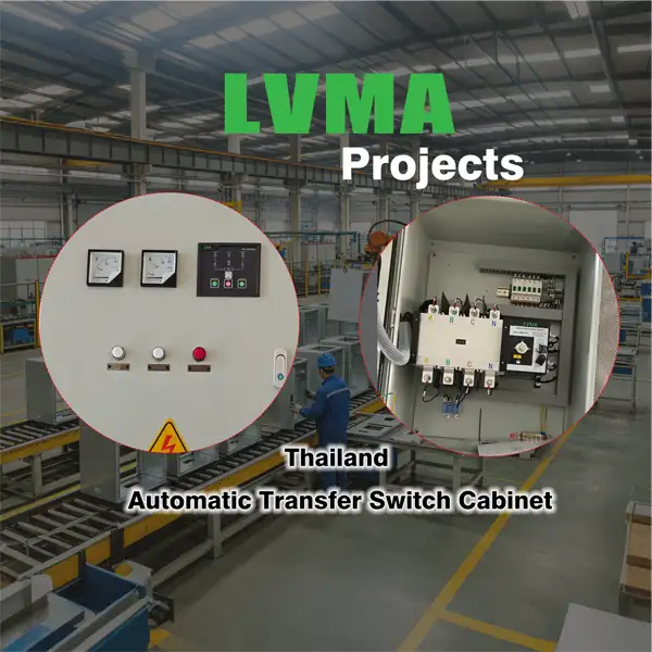
Front‑door Human‑Machine Interface Components (visible on the closed outer cabinet door in the first photo)
- Multifunction power meter: Continuously monitors three‑phase voltage, line current, active power, cumulative energy consumption and power factor at the incoming feeder side, supporting energy auditing and pre‑emptive anomaly alerting.
- Tri‑color status indicator lamps (yellow, green, red): Standard operational logic: green = healthy energization of the primary utility feed; yellow = standby backup supply is live; red = fault alarm triggered by supply undervoltage or switch malfunction.
- High‑voltage electric shock warning decals: Mandatory safety reminders prohibiting cabinet door opening and contact with live busbars / breakers while the panel remains energized.
- Dual‑layer inner door assembly (demonstrated in the third photograph): A transparent viewing window on the inner partition permits visual confirmation of ATS operating state without door disassembly. The locked inner barrier physically restricts accidental contact with energized assemblies to elevate shock hazard mitigation.
| No. | Component Name | Model Specification | Quantity | Manufacturer | Function Description |
|---|---|---|---|---|---|
| 1 | Main Distribution Panel Cabinet | XL-21 | 1 Set | Customized | Low-voltage power distribution enclosure, cold-rolled steel plate, IP30 protection |
| 2 | Automatic Transfer Switch (ATS) | LMQ2CB-630/3P | 1 Unit | LVMA Electric | Automatic switching between normal and standby power supply, with manual operation function |
| 3 | Main Molded Case Circuit Breaker (MCCB) | EZD630E3600K | 1 Unit | Schneider Electric | Overload and short-circuit protection for the entire distribution system |
| 4 | Branch MCCB (Power) | EZD250E3200N | 1 Units | Schneider Electric | Power supply and protection for large-power equipment |
| 5 | Branch MCCB (Lighting) | EZD160E3125N | 4 Units | Schneider Electric | Power supply and protection for lighting and small-power loads |
| 6 | Branch MCCB (Lighting) | EZD100E3100N | 5 Units | Schneider Electric | Power supply and protection for lighting and small-power loads |
| 7 | Multifunction Power Meter | METSEDM3100C | 1 Unit | Schneider Electric | Real-time monitoring of voltage, current, power, energy and power factor |
| 8 | Status Indicator Lamps | 22mm LED, Red/Green/Yellow | 3 Pcs | Schneider Electric | Power supply status and fault alarm indication |
3. Built‑in Electrical Safety Merits
- Dual‑stage door isolation: An outer full‑size access door paired with compartmentalized inner partition doors creates redundant physical shielding. Routine inspection can be completed without fully exposing high‑voltage internals, drastically lowering electric shock risks. Lockable door latches accommodate lockout‑tagout (LOTO) protocols for powered‑down service procedures.
- Insulated busbar jacketing: Main trunk and branch copper busbars are sheathed with color‑coded insulating sleeves, eliminating cross‑phase short circuits caused by exposed conductive metal or stray foreign debris bridging live conductors.
- Independent cabinet locking hardware: Latched locked doors bar unauthorized personnel from tampering with configured distribution circuits.
- Standardized phase color coding: Phase conductors and the neutral wire adhere to international wiring color norms, cutting the risk of reversed phasing during field wiring and subsequent troubleshooting works.
4. Applicable Scenarios, Strengths & Drawbacks
Suitable Deployment Use Cases
- Primary feeder switchgear for small‑to‑medium manufacturing workshops and commercial strip‑mall electrical rooms;
- Sites with dual utility feed provisions (fire protection equipment inside industrial facilities, data server racks, warehouse lighting and power networks);
- Bulk power intake distribution points servicing low‑rise segments of commercial multi‑story buildings.
Competitive Advantages
- ATS‑facilitated automatic backup power transfer strengthens supply resilience. Hierarchical breaker tripping confines service disruptions to affected faulted zones.
- The mass‑produced XL‑21 cabinet platform simplifies spare part sourcing, circuit expansion and component replacement with lowered lifecycle expenditure. Dual partition door architecture reinforces operator safety margins.
- Externally mounted metering hardware and status lamps allow field technicians to diagnose supply anomalies rapidly, accelerating fault resolution turnaround times.
Limitations & Improvement Recommendations
- Stock enclosure ingress protection ratings only qualify deployment inside dry indoor electrical rooms; direct outdoor exposed installation is forbidden. Cabinet dehumidification heating assemblies are advised for moisture‑prone operating environments.
- For remote supervisory integration, fit RS485 communication expansion modules on the power meter to interface with centralized site energy management platforms. Residual current trip modules may be retrofitted to branch breakers for enhanced personnel electrocution hazard mitigation.
- Prior to prolonged high‑current commissioning, re‑torque all busbar bolted joints to mitigate abnormal thermal runaway stemming from loose fasteners.
5. Preventive Maintenance Guidelines
- Periodic walkthrough inspections: Verify meter readings and indicator lamp status, audit the cabinet for abnormal acoustic noise and localized overheating on busbar assemblies.
- Scheduled biannual / annual servicing (every 6–12 months): Perform bolt torque retightening on busbar and breaker terminals during locked‑out power downtime, vacuum accumulated cabinet dust, and validate seamless automatic ATS source transfer actuation via functional testing.
- Fault tripping troubleshooting protocol: Isolated branch breaker trips warrant root‑cause investigation of short‑circuit faults or load overloading on the dedicated downstream circuit. Main breaker activation mandates system‑wide screening for phase‑to‑ground and cross‑phase short‑circuit defects. Recurrent ATS source cycling necessitates stability verification across both independent utility supply feeds.

LVMA Project | Philippines 600A Customized Main Distribution Panel
The client is a local EPC contractor in the Philippines undertaking the construction of mid-rise commercial buildings in Metro Manila. Reliable power is needed to power the building. The project encountered several typical local power challenges during the planning phase:
Manila’s tropical climate brings consistently high humidity and sporadic outdoor rain splashes, and common thin-gauge electrical cabinets quickly rust, increasing the risk of short circuits and electric shock.
Local inspectors enforce strict Philippine Electrical Code (PEC) rules, including circuit isolation, mandatory shock warning signs, standardized wiring color coding, and dedicated grounding infrastructure. Mass-produced imitation cabinets have repeatedly failed municipal safety audits.
Frequent grid voltage fluctuations at urban construction sites in Metro Manila create overload risks; isolated branch circuit protection is needed to prevent a single circuit failure from causing an entire building to lose power
The contractor commissioned our factory to create a fully custom floor-standing distribution cabinet designed to address all of the above pain points and successfully pass official electrical inspections.
Customized cabinet design & hardware breakdown (with product photos)
Exterior cabinet (second photo)
The shell is made of thick cold-rolled steel plate, anti-scratch and anti-rust powder coating, double-layer design, size 1200*1900*600, box thickness 1.5mm. The front panel integrates a digital multi-function power meter for real-time grid voltage, current and load monitoring. Three color-coded indicators provide intuitive status alerts: yellow indicates standby power status, green indicates normal operation, and red indicates circuit fault alarm. Standard yellow “Danger Electric Shock” warning sticker meets Philippine occupational safety labeling requirements and has lockable rotating handles on both sides to limit unauthorized access to the cabinet.
2. Tiered Internal Hardware Breakdown (Power flow sequence: incoming supply → outgoing feeders)
Top Tier: LMQ2CB-630/3P Automatic Transfer Switch (ATS)
- Function: Interfaces with two independent utility feeds (normal supply + standby backup supply). It switches power to the backup feed automatically upon mains outage or abnormal voltage deviation to sustain power delivery for downstream critical loads, fitting premises with zero tolerance for blackouts such as production plants, server rooms and retail outlets. A manual rotary selector is integrated for forced source switching and full circuit isolation during maintenance work.
- Wiring standard: Three‑phase busbars follow industry color coding (yellow for Phase A, green for Phase B, red for Phase C, blue for neutral conductor). Tin plating on copper busbars mitigates resistive heat generation under high‑current operating conditions.
Middle Tier: Main Molded Case Circuit Breaker (MCCB)
- Protection capabilities: Built‑in instantaneous short‑circuit tripping and time‑delayed overload tripping mechanisms cut off power supply to the whole cabinet promptly during short‑circuit faults or sustained overloading, stopping fault propagation across the distribution network. Auxiliary attachments including residual current and undervoltage trip coils can be fitted on demand.
Bottom Tier: Multiple Branch MCCBs
- Zoned power supply: Separate breakers serve workshop machinery, general lighting and dedicated power circuits. Tripping on one isolated branch will not interrupt power to other operational circuits, limiting outage scope and streamlining fault diagnostics.
- Coordinated selective tripping hierarchy: ATS (source switching) → main MCCB (system‑wide fault protection) → branch MCCBs (individual load safeguarding). This three‑tier scheme prevents unwanted upstream over‑tripping during localized circuit faults.
Front‑door Human‑Machine Interface Components (visible on the closed outer cabinet door in the first photo)
- Multifunction power meter: Continuously monitors three‑phase voltage, line current, active power, cumulative energy consumption and power factor at the incoming feeder side, supporting energy auditing and pre‑emptive anomaly alerting.
- Tri‑color status indicator lamps (yellow, green, red): Standard operational logic: green = healthy energization of the primary utility feed; yellow = standby backup supply is live; red = fault alarm triggered by supply undervoltage or switch malfunction.
- High‑voltage electric shock warning decals: Mandatory safety reminders prohibiting cabinet door opening and contact with live busbars / breakers while the panel remains energized.
- Dual‑layer inner door assembly (demonstrated in the third photograph): A transparent viewing window on the inner partition permits visual confirmation of ATS operating state without door disassembly. The locked inner barrier physically restricts accidental contact with energized assemblies to elevate shock hazard mitigation.
| No. | Component Name | Model Specification | Quantity | Manufacturer | Function Description |
|---|---|---|---|---|---|
| 1 | Main Distribution Panel Cabinet | XL-21 | 1 Set | Customized | Low-voltage power distribution enclosure, cold-rolled steel plate, IP30 protection |
| 2 | Automatic Transfer Switch (ATS) | LMQ2CB-630/3P | 1 Unit | LVMA Electric | Automatic switching between normal and standby power supply, with manual operation function |
| 3 | Main Molded Case Circuit Breaker (MCCB) | EZD630E3600K | 1 Unit | Schneider Electric | Overload and short-circuit protection for the entire distribution system |
| 4 | Branch MCCB (Power) | EZD250E3200N | 1 Units | Schneider Electric | Power supply and protection for large-power equipment |
| 5 | Branch MCCB (Lighting) | EZD160E3125N | 4 Units | Schneider Electric | Power supply and protection for lighting and small-power loads |
| 6 | Branch MCCB (Lighting) | EZD100E3100N | 5 Units | Schneider Electric | Power supply and protection for lighting and small-power loads |
| 7 | Multifunction Power Meter | METSEDM3100C | 1 Unit | Schneider Electric | Real-time monitoring of voltage, current, power, energy and power factor |
| 8 | Status Indicator Lamps | 22mm LED, Red/Green/Yellow | 3 Pcs | Schneider Electric | Power supply status and fault alarm indication |
3. Built‑in Electrical Safety Merits
- Dual‑stage door isolation: An outer full‑size access door paired with compartmentalized inner partition doors creates redundant physical shielding. Routine inspection can be completed without fully exposing high‑voltage internals, drastically lowering electric shock risks. Lockable door latches accommodate lockout‑tagout (LOTO) protocols for powered‑down service procedures.
- Insulated busbar jacketing: Main trunk and branch copper busbars are sheathed with color‑coded insulating sleeves, eliminating cross‑phase short circuits caused by exposed conductive metal or stray foreign debris bridging live conductors.
- Independent cabinet locking hardware: Latched locked doors bar unauthorized personnel from tampering with configured distribution circuits.
- Standardized phase color coding: Phase conductors and the neutral wire adhere to international wiring color norms, cutting the risk of reversed phasing during field wiring and subsequent troubleshooting works.
4. Applicable Scenarios, Strengths & Drawbacks
Suitable Deployment Use Cases
- Primary feeder switchgear for small‑to‑medium manufacturing workshops and commercial strip‑mall electrical rooms;
- Sites with dual utility feed provisions (fire protection equipment inside industrial facilities, data server racks, warehouse lighting and power networks);
- Bulk power intake distribution points servicing low‑rise segments of commercial multi‑story buildings.
Competitive Advantages
- ATS‑facilitated automatic backup power transfer strengthens supply resilience. Hierarchical breaker tripping confines service disruptions to affected faulted zones.
- The mass‑produced XL‑21 cabinet platform simplifies spare part sourcing, circuit expansion and component replacement with lowered lifecycle expenditure. Dual partition door architecture reinforces operator safety margins.
- Externally mounted metering hardware and status lamps allow field technicians to diagnose supply anomalies rapidly, accelerating fault resolution turnaround times.
Limitations & Improvement Recommendations
- Stock enclosure ingress protection ratings only qualify deployment inside dry indoor electrical rooms; direct outdoor exposed installation is forbidden. Cabinet dehumidification heating assemblies are advised for moisture‑prone operating environments.
- For remote supervisory integration, fit RS485 communication expansion modules on the power meter to interface with centralized site energy management platforms. Residual current trip modules may be retrofitted to branch breakers for enhanced personnel electrocution hazard mitigation.
- Prior to prolonged high‑current commissioning, re‑torque all busbar bolted joints to mitigate abnormal thermal runaway stemming from loose fasteners.
5. Preventive Maintenance Guidelines
- Periodic walkthrough inspections: Verify meter readings and indicator lamp status, audit the cabinet for abnormal acoustic noise and localized overheating on busbar assemblies.
- Scheduled biannual / annual servicing (every 6–12 months): Perform bolt torque retightening on busbar and breaker terminals during locked‑out power downtime, vacuum accumulated cabinet dust, and validate seamless automatic ATS source transfer actuation via functional testing.
- Fault tripping troubleshooting protocol: Isolated branch breaker trips warrant root‑cause investigation of short‑circuit faults or load overloading on the dedicated downstream circuit. Main breaker activation mandates system‑wide screening for phase‑to‑ground and cross‑phase short‑circuit defects. Recurrent ATS source cycling necessitates stability verification across both independent utility supply feeds.
Contact Us

Contact Us
Have questions about our products or services? Our team is here to help you with any inquiries.