

What is a Contactor?
What is a Contactor?
Introduction
Modern industrial, commercial and renewable‑energy systems rely heavily on safe remote power switching. Electricians, panel builders and system integrators often encounter contactors inside motor control cabinets, solar inverter combiner boxes and automation panels. Many people mix up contactors and relays, even though they serve different power‑handling purposesIEEE Techn….
A contactor is an electromagnetic switching device built to switch high‑current loads remotely using a low‑voltage control signal. This article explains contactor fundamentals, internal structure, operating logic, main types, comparison with relays, typical applications and practical selection advice for your next electrical project.
What Exactly Is a Contactor?
A contactor is an electrically controlled switch designed to make or break high‑power electrical circuits under normal load conditions, complying with IEC 60947‑4‑1 international standard. It uses a small control‑circuit power supply to open and close heavy‑duty main contacts that carry large operating currents.
Unlike manual switches, contactors support frequent, automated on‑off cycles triggered by PLCs, timers, sensors or push‑buttons. They are widely used whenever you need to remotely start, stop or isolate heavy‑duty equipment such as motors, heaters and battery energy‑storage units.
Key internal components of a standard electromagnetic contactor:
- Electromagnetic coil: Creates magnetic force when energized by low‑voltage control power.
- Movable armature: Driven by the coil magnet to open or close main contacts.
- Main power contacts: Heavy‑duty conductive points for high‑current load circuits.
- Auxiliary contacts: Small‑capacity contacts for control‑circuit logic and status feedback.
- Arc‑chute chamber: Suppresses electric arcs generated while breaking high‑current circuits to protect contact surfaces and prevent fire risks.
- Return spring: Forces contacts open once coil power cuts off.
How Does a Contactor Work?
The contactor runs on basic electromagnetic principles.
When control‑circuit voltage applies to the coil, electric current generates a magnetic field. This magnetic force pulls the movable armature toward the fixed core, pushing movable main contacts against fixed contacts. The main power circuit closes, and power flows through the connected load. Auxiliary contacts simultaneously switch state for signal feedback.
Once control power to the coil is removed, the magnetic field disappears. The return spring pushes the armature back, separating main contacts and disconnecting the main load circuit.
Arc suppression inside the arc‑chute is critical: every time high‑current contacts separate, electric arcs appear. Arc‑chutes split and cool arcs rapidly, extending contact service life and improving operational safety.
Important note: A standard contactor itself does NOT provide overload or short‑circuit protection. It needs to pair with MCB, MCCB or thermal overload relays for full circuit safety.
Contactor vs Relay: What Are the Real Differences?
At first glance, contactors and relays look similar: both use coils to drive contact switching. But they are engineered for completely different current ranges and mission profiles.
| Feature | Contactor | Relay |
|---|---|---|
| Main‑circuit current | 9A up to thousands of Amperes | Normally below 10 A |
| Core purpose | Switch high‑power loads (motors, heaters, solar power) | Switch low‑power control signals and logic circuits |
| Arc‑suppression | Built‑in arc‑chute chamber | Usually no dedicated arc suppression |
| Typical duty | Frequent heavy‑load switching | Signal interlocking, logic triggering |
| Mounting | DIN‑rail, panel mounting | DIN‑rail, PCB, socket mounting |
Simple rule of thumb: Use a relay for control‑signal logic. Use a contactor when you need to switch high‑voltage or high‑current power‑circuits.
Main Types of Contactors
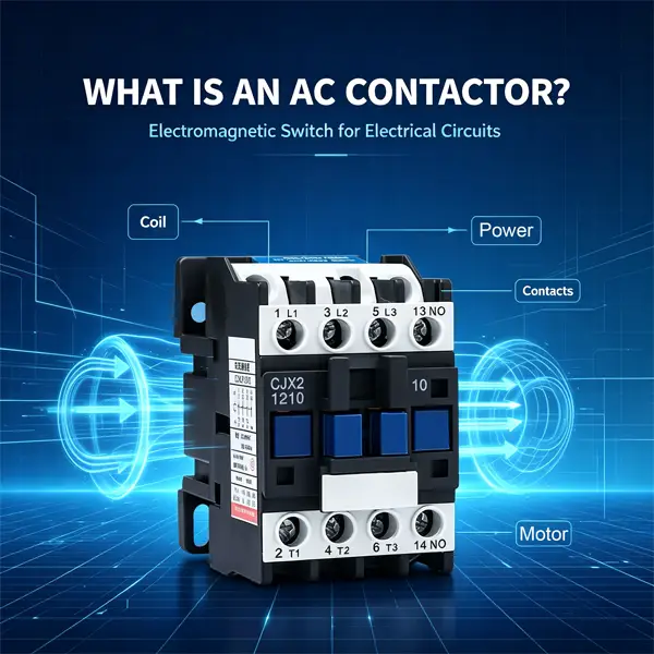
AC Contactor
AC contactors are the most common type, built for alternating‑current loads. AC current crosses zero in every cycle, which naturally weakens electric arcs during contact opening. Widely used for three‑phase motors, pumps, fans, commercial lighting and HVAC equipment.
DC Contactor
DC contactors handle direct‑current circuits such as solar PV systems, battery energy storage and DC charging equipment. DC current has no natural zero‑crossing point, so DC contactors adopt enhanced arc blow‑out structures and larger contact gaps to extinguish persistent DC arcs. Never directly replace a DC contactor with an AC‑rated model for DC‑side circuits, as severe arcing will cause premature failure or safety hazards.
Solid‑State Contactor (SSC)
No moving mechanical parts. It switches loads via semiconductor components. Benefits include silent operation, extremely fast switching speed and long lifespan. Suitable for high‑cycle‑rate applications, yet requires proper heat dissipation.
Vacuum Contactor
Contacts operate inside sealed vacuum chambers. Outstanding arc‑extinguishing performance, applied mainly for medium‑voltage heavy‑industry scenarios.
Key Benefits of Using Contactors
- Remote automated control: Start‑stop heavy loads remotely via PLC, sensors or control panels without manual high‑voltage operation.
- Support frequent switching cycles: Designed for repeated on‑off operations for motors and dynamic loads.
- Low‑power control of high‑power circuits: Small coil power safely manages huge main‑circuit currents.
- Flexible system integration: Auxiliary contacts deliver running‑status feedback for automation logic.
- Broad compatibility: Available across massive ranges of coil voltages and main‑circuit ratings for residential‑commercial‑industrial‑renewable‑energy projects.
Common Real‑World Applications
- Industrial automation: Three‑phase motor control for conveyors, compressors, pumps, machine tools, paired with overload relays for motor protection.
- Commercial buildings: Large‑scale lighting control, HVAC systems, water‑heating equipment.
- Renewable energy: Solar PV combiner cabinets, battery energy‑storage systems, inverter DC‑side isolation, off‑grid power management. DC‑rated contactors are essential for battery bank switching tasks.
- Light‑industry & workshops: Heavy machinery power control, welding‑equipment circuits.
- Transport & charging: EV charging stations, battery‑powered equipment main‑circuit switching.
Practical Contactor Selection Checklist
Before ordering contactors, verify these core parameters against your project requirements:
- Main‑circuit rated current and voltage: Match actual load working conditions; remember to apply proper derating.
- Utilization category: AC‑3 for general motor switching; AC‑4 for heavy‑duty motor frequent start‑stop tasks.
- Coil control voltage: 24VAC, 24VDC, 110VAC, 220VAC are popular options, must match your control‑circuit supply.
- AC‑type or DC‑type: Select DC‑specific contactors for battery and solar DC‑side circuits.
- Auxiliary contacts quantity: Confirm NO / NC auxiliary contact count for feedback and interlocking logic.
- Certification: IEC 60947‑4‑1 compliance for global export projects.
Frequently Asked Questions
Q1: Can a contactor work alone without protection devices?
A: A contactor only performs switching. It cannot cut off overload or short‑circuit faults. Always cooperate with circuit breakers or thermal overload relays to protect loads and wiring.
Q2: Can I use an AC contactor on DC circuits?
A: Not recommended for high‑current DC applications. AC contactors lack sufficient DC arc‑suppression capacity, contacts will burn quickly and create safety risks.
Q3: Why does my contactor make loud noise during operation?
A: Most‑often caused by coil‑voltage deviation, dirty armature surfaces or mechanical wear. Check control‑circuit voltage and perform regular maintenance.
Q4: What causes contactor contacts to burn out?
A: Excessive overcurrent, wrong utilization category rating, insufficient arc suppression, or frequent short‑circuit fault events.
Conclusion
Contactors are fundamental building blocks within low‑voltage power systems. By enabling low‑signal remote control over high‑current loads, they make automated motor operation, industrial machinery and modern solar‑storage systems practical and safe.
When selecting a contactor, distinguish carefully between AC and DC models, confirm utilization category and coil voltage, and combine it with proper overcurrent‑protection components. Correct specification improves equipment reliability and extends component service life for your commercial, industrial or renewable‑energy projects.
If you source contactors for panel‑building or renewable‑energy projects, always cross‑check datasheet parameters and international certification against local electrical codes.
Share This Article
Follow Us
Introduction
Modern industrial, commercial and renewable‑energy systems rely heavily on safe remote power switching. Electricians, panel builders and system integrators often encounter contactors inside motor control cabinets, solar inverter combiner boxes and automation panels. Many people mix up contactors and relays, even though they serve different power‑handling purposesIEEE Techn….
A contactor is an electromagnetic switching device built to switch high‑current loads remotely using a low‑voltage control signal. This article explains contactor fundamentals, internal structure, operating logic, main types, comparison with relays, typical applications and practical selection advice for your next electrical project.
What Exactly Is a Contactor?
A contactor is an electrically controlled switch designed to make or break high‑power electrical circuits under normal load conditions, complying with IEC 60947‑4‑1 international standard. It uses a small control‑circuit power supply to open and close heavy‑duty main contacts that carry large operating currents.
Unlike manual switches, contactors support frequent, automated on‑off cycles triggered by PLCs, timers, sensors or push‑buttons. They are widely used whenever you need to remotely start, stop or isolate heavy‑duty equipment such as motors, heaters and battery energy‑storage units.
Key internal components of a standard electromagnetic contactor:
- Electromagnetic coil: Creates magnetic force when energized by low‑voltage control power.
- Movable armature: Driven by the coil magnet to open or close main contacts.
- Main power contacts: Heavy‑duty conductive points for high‑current load circuits.
- Auxiliary contacts: Small‑capacity contacts for control‑circuit logic and status feedback.
- Arc‑chute chamber: Suppresses electric arcs generated while breaking high‑current circuits to protect contact surfaces and prevent fire risks.
- Return spring: Forces contacts open once coil power cuts off.
How Does a Contactor Work?
The contactor runs on basic electromagnetic principles.
When control‑circuit voltage applies to the coil, electric current generates a magnetic field. This magnetic force pulls the movable armature toward the fixed core, pushing movable main contacts against fixed contacts. The main power circuit closes, and power flows through the connected load. Auxiliary contacts simultaneously switch state for signal feedback.
Once control power to the coil is removed, the magnetic field disappears. The return spring pushes the armature back, separating main contacts and disconnecting the main load circuit.
Arc suppression inside the arc‑chute is critical: every time high‑current contacts separate, electric arcs appear. Arc‑chutes split and cool arcs rapidly, extending contact service life and improving operational safety.
Important note: A standard contactor itself does NOT provide overload or short‑circuit protection. It needs to pair with MCB, MCCB or thermal overload relays for full circuit safety.
Contactor vs Relay: What Are the Real Differences?
At first glance, contactors and relays look similar: both use coils to drive contact switching. But they are engineered for completely different current ranges and mission profiles.
| Feature | Contactor | Relay |
|---|---|---|
| Main‑circuit current | 9A up to thousands of Amperes | Normally below 10 A |
| Core purpose | Switch high‑power loads (motors, heaters, solar power) | Switch low‑power control signals and logic circuits |
| Arc‑suppression | Built‑in arc‑chute chamber | Usually no dedicated arc suppression |
| Typical duty | Frequent heavy‑load switching | Signal interlocking, logic triggering |
| Mounting | DIN‑rail, panel mounting | DIN‑rail, PCB, socket mounting |
Simple rule of thumb: Use a relay for control‑signal logic. Use a contactor when you need to switch high‑voltage or high‑current power‑circuits.
Main Types of Contactors
AC Contactor
AC contactors are the most common type, built for alternating‑current loads. AC current crosses zero in every cycle, which naturally weakens electric arcs during contact opening. Widely used for three‑phase motors, pumps, fans, commercial lighting and HVAC equipment.
DC Contactor
DC contactors handle direct‑current circuits such as solar PV systems, battery energy storage and DC charging equipment. DC current has no natural zero‑crossing point, so DC contactors adopt enhanced arc blow‑out structures and larger contact gaps to extinguish persistent DC arcs. Never directly replace a DC contactor with an AC‑rated model for DC‑side circuits, as severe arcing will cause premature failure or safety hazards.
Solid‑State Contactor (SSC)
No moving mechanical parts. It switches loads via semiconductor components. Benefits include silent operation, extremely fast switching speed and long lifespan. Suitable for high‑cycle‑rate applications, yet requires proper heat dissipation.
Vacuum Contactor
Contacts operate inside sealed vacuum chambers. Outstanding arc‑extinguishing performance, applied mainly for medium‑voltage heavy‑industry scenarios.
Key Benefits of Using Contactors
- Remote automated control: Start‑stop heavy loads remotely via PLC, sensors or control panels without manual high‑voltage operation.
- Support frequent switching cycles: Designed for repeated on‑off operations for motors and dynamic loads.
- Low‑power control of high‑power circuits: Small coil power safely manages huge main‑circuit currents.
- Flexible system integration: Auxiliary contacts deliver running‑status feedback for automation logic.
- Broad compatibility: Available across massive ranges of coil voltages and main‑circuit ratings for residential‑commercial‑industrial‑renewable‑energy projects.
Common Real‑World Applications
- Industrial automation: Three‑phase motor control for conveyors, compressors, pumps, machine tools, paired with overload relays for motor protection.
- Commercial buildings: Large‑scale lighting control, HVAC systems, water‑heating equipment.
- Renewable energy: Solar PV combiner cabinets, battery energy‑storage systems, inverter DC‑side isolation, off‑grid power management. DC‑rated contactors are essential for battery bank switching tasks.
- Light‑industry & workshops: Heavy machinery power control, welding‑equipment circuits.
- Transport & charging: EV charging stations, battery‑powered equipment main‑circuit switching.
Practical Contactor Selection Checklist
Before ordering contactors, verify these core parameters against your project requirements:
- Main‑circuit rated current and voltage: Match actual load working conditions; remember to apply proper derating.
- Utilization category: AC‑3 for general motor switching; AC‑4 for heavy‑duty motor frequent start‑stop tasks.
- Coil control voltage: 24VAC, 24VDC, 110VAC, 220VAC are popular options, must match your control‑circuit supply.
- AC‑type or DC‑type: Select DC‑specific contactors for battery and solar DC‑side circuits.
- Auxiliary contacts quantity: Confirm NO / NC auxiliary contact count for feedback and interlocking logic.
- Certification: IEC 60947‑4‑1 compliance for global export projects.
Frequently Asked Questions
Q1: Can a contactor work alone without protection devices?
A: A contactor only performs switching. It cannot cut off overload or short‑circuit faults. Always cooperate with circuit breakers or thermal overload relays to protect loads and wiring.
Q2: Can I use an AC contactor on DC circuits?
A: Not recommended for high‑current DC applications. AC contactors lack sufficient DC arc‑suppression capacity, contacts will burn quickly and create safety risks.
Q3: Why does my contactor make loud noise during operation?
A: Most‑often caused by coil‑voltage deviation, dirty armature surfaces or mechanical wear. Check control‑circuit voltage and perform regular maintenance.
Q4: What causes contactor contacts to burn out?
A: Excessive overcurrent, wrong utilization category rating, insufficient arc suppression, or frequent short‑circuit fault events.
Conclusion
Contactors are fundamental building blocks within low‑voltage power systems. By enabling low‑signal remote control over high‑current loads, they make automated motor operation, industrial machinery and modern solar‑storage systems practical and safe.
When selecting a contactor, distinguish carefully between AC and DC models, confirm utilization category and coil voltage, and combine it with proper overcurrent‑protection components. Correct specification improves equipment reliability and extends component service life for your commercial, industrial or renewable‑energy projects.
If you source contactors for panel‑building or renewable‑energy projects, always cross‑check datasheet parameters and international certification against local electrical codes.
Contact Us
Related Blog


Contact Us
Have questions about our products or services? Our team is here to help you with any inquiries.