

Voltage Protector Setup | Full P01‑P19 Parameter Guide
Voltage Protector Setup | Full P01‑P19 Parameter Guide
Have you ever come home to find a broken refrigerator, burnt air‑conditioner compressor or dead television — while your standard circuit breaker remains untouched? Unstable mains voltage is often the hidden culprit.
Traditional MCB breakers only protect against short‑circuits and over‑current. They cannot detect sustained high‑voltage surges (overvoltage) or low‑voltage brown‑outs. Surge power strips absorb micro‑second lightning spikes, but offer zero defence against long‑duration voltage drift caused by ageing grid infrastructure, neutral wire faults, or power restoration after blackouts.
This is where the LMGQ1 dual‑display adjustable DIN‑rail protector fills the safety gap. This compact device monitors both mains voltage and load current in real‑time. It automatically cuts power when readings move outside your custom‑configured safe boundaries, and can restore power automatically once conditions stabilise. It combines over‑voltage, under‑voltage and over‑current protection into one,protect your electrical products.
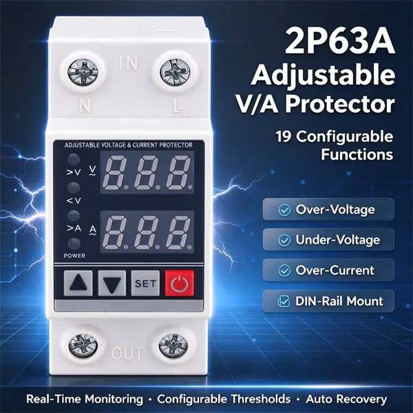
Why You Need LMGQ1 V/A Protector
Standard MCB circuit breakers only react for short‑circuit and over‑current faults. They cannot detect dangerous high‑voltage spikes or low‑voltage brown‑outs that burn compressors, power supplies and motor‑driven equipment. Surge protective devices only absorb micro‑second lightning surges, they cannot handle sustained abnormal voltage lasting multiple seconds.
The 2P63A protector continuously monitors supply quality. It cuts off power automatically when voltage or current exceeds custom‑set thresholds. After fault conditions clear, it can restore power automatically without manual operation. Perfect for homes, retail shops, solar battery banks and remote unattended sites.
Key Technical Specifications
| Item | Specification |
|---|---|
| Model Name | LMGQ1 |
| Supply Terminals | 1P+N(L, N) |
| Rated Voltage | AC 220V; DC 80‑300V |
| Frequency | 40/50/60/70Hz |
| Overvoltage Setting | AC 130‑300V |
| Undervoltage Setting | AC 80‑210V |
| Voltage Hysteresis | 5V |
| Overvoltage Trip Delay | 0.5s default (adjustable) |
| Voltage Accuracy | <1% |
| Max Phase Voltage | 350V |
| Max Operating Current | 40A /63A/80A/100A |
| Working Altitude | ≤2000 m |
| Ambient Temperature | ‑25°C ~ +50°C |
| Dimension | 85 × 36 × 66 mm |
Core Protective Features
- Dual‑Display Real‑Time Monitoring Front‑panel dual digital screens show live voltage and load current (current display disabled for DC input). Status LED indicators mark over‑voltage (>V), under‑voltage (<V), over‑current (>A) and normal power status. You can diagnose grid or battery‑system issues without external multimeters.
- Adjustable Over‑Voltage & Under‑Voltage Protection Trip thresholds are fully configurable instead of fixed factory values. Built‑in 5 V voltage hysteresis plus independent recovery thresholds prevent rapid relay on‑off cycling caused by minor voltage fluctuations.
- Configurable Timing Logic Power‑on delay, fault trip delay and fault recovery delay are fully adjustable. Filter short harmless voltage blips and avoid nuisance tripping; hold off power restoration to let grid or battery voltage stabilise.
- Adjustable Over‑Current Protection Over‑current threshold ranges 40 / 63 / 80 / 100A. Adjustable trip delay helps ignore short‑time motor inrush current during startup. Built‑in fault counter logs over‑current events for troubleshooting recurring overload issues.
- Auto‑Reset / Manual Reset Selectable Switch between automatic self‑recovery after faults or manual reset mode, for unattended sites or high‑risk equipment requiring human inspection before power resumes.
- Parameter Password Lock Lock menu settings to prevent accidental or unauthorised modification of safety thresholds.
Full Explanation of All P1‑P19 Parameters
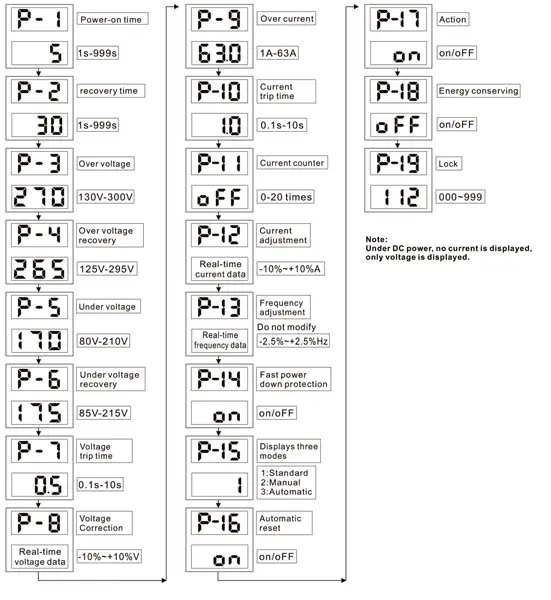
Access menu by pressing the SET button. Wrong configuration may trigger nuisance tripping or disable safety functions.
P‑1 Power‑on time
- Range:1‑999s
- Default:5s
- Function: Power‑on delay after power failure. The protector waits this time before closing output after power returns.
- Use‑case: Prevent simultaneous inrush of multiple appliances after blackout. Extend value for solar off‑grid cabins.
P‑2 Recovery time
‑ Range:1‑999s ‑ Default:30s ‑ Function: General fault recovery hold‑off timer. After voltage/current returns to safe range, wait this countdown before restoring power to loads.
P‑3 Over voltage
‑ Range:130‑300V (AC/DC) ‑ Default:270V ‑ Function: Over‑voltage trip threshold. When input voltage rises above this value, protection will trigger after P‑7 voltage trip time.
P‑4 Over voltage recovery
‑ Range:125‑295V ‑ Default:265V ‑ Function: Over‑voltage recovery threshold. After over‑voltage trip, voltage must drop below this value to start recovery countdown. Always maintain a clear voltage gap versus P‑3 to avoid relay cycling.
P‑5 Under voltage
‑ Range:80‑210V (AC/DC) ‑ Default:170V ‑ Function: Under‑voltage trip threshold. When supply voltage falls below this value, unit trips after P‑7 trip delay. Protects motors from brown‑out burnout.
P‑6 Under voltage recovery
‑ Range:85‑215V ‑ Default:175V ‑ Function: Undervoltage recovery threshold. Voltage must rise higher than this setting to enable auto‑recovery after undervoltage fault. Keep proper gap above P‑5 value.
P‑7 Voltage trip time
‑ Range:0.1‑10s ‑ Default:0.5s ‑ Function: Voltage fault detection delay. Abnormal voltage must persist for this time before cutting power. Short transient spikes or dips will be ignored. Increase value if you get nuisance tripping.
P‑8 Voltage Correction
‑ Range:‑10% ~ +10% ‑ Function: Voltage measurement calibration offset.
⚠️ End‑users do NOT modify. Factory‑only calibration. Wrong offset will make all voltage thresholds inaccurate. Only qualified technicians with reference meters should adjust.
P‑9 Over current
‑ Range:1‑63A ‑ Default:63A ‑ Function: Over‑current trip threshold. When load current exceeds this value, over‑current protection activates after P‑10 current trip time. Note: Over‑current function does not work on DC power supply.
P‑10 Current trip time
‑ Range:0.1‑10s ‑ Default:1.0s ‑ Function: Over‑current trip delay. Bypass brief motor startup inrush current. Raise value for compressor, pump loads to avoid false over‑current trips.
P‑11 Current counter
‑ Range:0‑20 times / OFF ‑ Default:OFF ‑ Function: Counts over‑current fault occurrences. Set OFF to disable counting. Helpful for rental houses and workshops to diagnose repeated overload problems.
P‑12 Current adjustment
‑ Range:‑10% ~ +10%A ‑ Function: Current reading calibration offset.
⚠️ Factory‑level setting, leave untouched for regular use. Incorrect adjustment causes wrong over‑current trigger points.
P‑13 Frequency adjustment
‑ Range:‑2.5% ~ +2.5%Hz ‑ Function: Power frequency calibration.
⚠️ Do not modify this parameter. For factory calibration purpose only.
P‑14 Fast power down protection
‑ Options:ON / OFF ‑ Default:ON ‑ Function: Full power‑loss protection. When input power completely cuts off, the protector will trip automatically. When power restores, P‑1 power‑on delay will execute before output closes. Prevents abrupt hard restart of appliances after total blackouts.
P‑15 Displays three modes
‑ Options:1=Standard /2=Manual /3=Automatic ‑ Default:1 ‑ 1. Standard: Fixed screen, always shows voltage and current readings. ‑ 2. Manual: User manually toggle display pages by buttons. ‑ 3. Automatic: Screen auto‑cycles through different readout pages.
P‑16 Automatic reset
‑ Options:ON / OFF ‑ Default:ON ‑ Function: Global auto‑reset master switch. ‑ ON: Automatically restore power once fault conditions clear, following recovery timers. Ideal for unattended holiday homes, solar sites. ‑ OFF: Manual reset required by pressing button after every fault trip. Use for high‑risk equipment requiring human inspection.
P‑17 Action
‑ Options:ON / OFF ‑ Default:ON ‑ ON: Normal protection mode, all voltage & current safety functions fully active. ‑ OFF: Knife / bypass mode. All protective functions disabled; device works only as manual on‑off switch.
⚠️ WARNING: Only use OFF for temporary testing. Never run normal loads under knife mode.
P‑18 Energy conserving
‑ Options:ON / OFF ‑ Default:OFF ‑ ON: Screen dims or powers off during idle time; press any button to wake display. Save power for low‑power DC solar systems. ‑ OFF: Display stays continuously lit for real‑time monitoring and troubleshooting.
P‑19 Lock
‑ Range:000‑999 ‑ Default:112 ‑ Function: Parameter lock password. ‑ Value=112: Unlocked, you can edit all parameters. ‑ Any value other than 112: Locked. You can view parameters, but cannot modify any settings.
After finishing configuration, change P‑19 away from 112 to lock safety settings, remember your custom password.
Who Should Use LMGQ1 V/A Protector
✅ Residential homes with unstable power supply Especially rural areas, locations with old utility infrastructure, properties hit by frequent brown‑outs and post‑outage voltage spikes. Protect compressors in fridges, washing machines and air‑conditioners.
✅ Small businesses & retail stores Protect POS hardware, refrigerated display units and lighting systems, avoid costly equipment downtime and business losses.
✅ Grid‑tied solar PV systems Add hardware‑level safety protection beyond the inverter’s built‑in software against grid voltage swings.
✅ Holiday homes & unattended remote cabins Auto‑reset functionality restores power automatically after grid faults with no on‑site personnel required.
✅ Workshops with motor‑driven machinery Prevent premature motor winding burnout caused by sustained low‑voltage operation.
V/A Protector vs MCB vs Surge Protection SPD
| Device | Protection Coverage | Limitations |
|---|---|---|
| MCB Circuit Breaker | Short‑circuit & overload over‑current | Cannot monitor voltage; no defence for over‑voltage / brown‑out damage |
| Surge SPD | Micro‑second lightning & switching spikes | Cannot handle sustained seconds‑long abnormal voltage |
| V/A Protector | Adjustable over‑voltage, under‑voltage, over‑current. Supports AC & DC input | DC mode no‑current measurement; not a replacement for MCB |
Best practice: Install MCB + SPD + V/A protector together for full‑layer electrical safety.
Installation & Configuration Critical Tips
- Install on standard 35 mm DIN‑rail inside distribution box. Strictly follow IN(input) and OUT(load) terminal labels, avoid reverse wiring.
- Keep sufficient voltage gap between trip value and recovery value (P‑3 vs P‑4; P‑5 vs P‑6). Too‑small gap causes rapid relay cycling.
- Calibration parameters P‑8, P‑12, P‑13 are factory‑only. Do not adjust unless you hold precise measuring instruments.
- If you get nuisance tripping, moderately increase P‑7 voltage trip time or P‑10 current trip time.
- After completing setup, set P‑19 password lock to prevent unintended parameter changes.
- P‑16 automatic reset is global master switch; it applies for both voltage‑related and current‑related faults.
FAQ
Q: Do I still need MCB after installing this voltage protector? A: Absolutely yes. This device handles voltage and over‑current protection, but MCB remains essential for short‑circuit fault protection. They work together as a complete safety system.
Q: Will it trip for every tiny voltage fluctuation? A: No. It has configurable trip delay and voltage hysteresis. Short‑lived minor grid deviations will not trigger power cut‑off.
Q: Can I disable auto‑reset and use manual reset mode? A: Yes. You can switch auto‑reset (P18 parameter) to OFF mode. After fault‑tripping, manual intervention is required to restore power.
Q: Can non‑electrician adjust parameters? A: Basic menu navigation is user‑friendly. But voltage‑safety settings should be configured or checked by a certified electrician. Use password‑lock feature once setup is finished to avoid unintended changes.
Q: Why can’t I edit parameters any more? A: Check P‑19 lock value. If it is not 112, menu is password‑locked. Enter correct password to unlock edit permission.
Q: What happens when P‑17 Action is set OFF? A: Knife mode is activated. All protective features are disabled. The device acts only as manual switch. Do not use for daily operation, only temporary testing.
Q: Why protector trips frequently without real fault? A: Check trip‑delay setting P‑7 and P‑10. Increase delay value to filter short‑time grid disturbances. Also verify there is enough gap between trip threshold and recovery threshold.
Final Thoughts
Many homeowners only realize voltage‑related risks after they pay for expensive appliance repairs or replacements. Circuit breakers and surge strips cannot cover all power‑grid risks.
Adjustable over‑under voltage protection gives you configurable, hardware‑level safety. Real‑time dual display, flexible trip/recovery delays, auto‑reset capability make LMGQ1 a practical upgrade for homes, workshops and solar‑powered sites where mains‑supply stability cannot be guaranteed.
A small investment in voltage protection can spare you hundreds or thousands in destroyed home appliances.
Share This Article
Follow Us
Have you ever come home to find a broken refrigerator, burnt air‑conditioner compressor or dead television — while your standard circuit breaker remains untouched? Unstable mains voltage is often the hidden culprit.
Traditional MCB breakers only protect against short‑circuits and over‑current. They cannot detect sustained high‑voltage surges (overvoltage) or low‑voltage brown‑outs. Surge power strips absorb micro‑second lightning spikes, but offer zero defence against long‑duration voltage drift caused by ageing grid infrastructure, neutral wire faults, or power restoration after blackouts.
This is where the LMGQ1 dual‑display adjustable DIN‑rail protector fills the safety gap. This compact device monitors both mains voltage and load current in real‑time. It automatically cuts power when readings move outside your custom‑configured safe boundaries, and can restore power automatically once conditions stabilise. It combines over‑voltage, under‑voltage and over‑current protection into one,protect your electrical products.
Why You Need LMGQ1 V/A Protector
Standard MCB circuit breakers only react for short‑circuit and over‑current faults. They cannot detect dangerous high‑voltage spikes or low‑voltage brown‑outs that burn compressors, power supplies and motor‑driven equipment. Surge protective devices only absorb micro‑second lightning surges, they cannot handle sustained abnormal voltage lasting multiple seconds.
The 2P63A protector continuously monitors supply quality. It cuts off power automatically when voltage or current exceeds custom‑set thresholds. After fault conditions clear, it can restore power automatically without manual operation. Perfect for homes, retail shops, solar battery banks and remote unattended sites.
Key Technical Specifications
| Item | Specification |
|---|---|
| Model Name | LMGQ1 |
| Supply Terminals | 1P+N(L, N) |
| Rated Voltage | AC 220V; DC 80‑300V |
| Frequency | 40/50/60/70Hz |
| Overvoltage Setting | AC 130‑300V |
| Undervoltage Setting | AC 80‑210V |
| Voltage Hysteresis | 5V |
| Overvoltage Trip Delay | 0.5s default (adjustable) |
| Voltage Accuracy | <1% |
| Max Phase Voltage | 350V |
| Max Operating Current | 40A /63A/80A/100A |
| Working Altitude | ≤2000 m |
| Ambient Temperature | ‑25°C ~ +50°C |
| Dimension | 85 × 36 × 66 mm |
Core Protective Features
- Dual‑Display Real‑Time Monitoring Front‑panel dual digital screens show live voltage and load current (current display disabled for DC input). Status LED indicators mark over‑voltage (>V), under‑voltage (<V), over‑current (>A) and normal power status. You can diagnose grid or battery‑system issues without external multimeters.
- Adjustable Over‑Voltage & Under‑Voltage Protection Trip thresholds are fully configurable instead of fixed factory values. Built‑in 5 V voltage hysteresis plus independent recovery thresholds prevent rapid relay on‑off cycling caused by minor voltage fluctuations.
- Configurable Timing Logic Power‑on delay, fault trip delay and fault recovery delay are fully adjustable. Filter short harmless voltage blips and avoid nuisance tripping; hold off power restoration to let grid or battery voltage stabilise.
- Adjustable Over‑Current Protection Over‑current threshold ranges 40 / 63 / 80 / 100A. Adjustable trip delay helps ignore short‑time motor inrush current during startup. Built‑in fault counter logs over‑current events for troubleshooting recurring overload issues.
- Auto‑Reset / Manual Reset Selectable Switch between automatic self‑recovery after faults or manual reset mode, for unattended sites or high‑risk equipment requiring human inspection before power resumes.
- Parameter Password Lock Lock menu settings to prevent accidental or unauthorised modification of safety thresholds.
Full Explanation of All P1‑P19 Parameters
Access menu by pressing the SET button. Wrong configuration may trigger nuisance tripping or disable safety functions.
P‑1 Power‑on time
- Range:1‑999s
- Default:5s
- Function: Power‑on delay after power failure. The protector waits this time before closing output after power returns.
- Use‑case: Prevent simultaneous inrush of multiple appliances after blackout. Extend value for solar off‑grid cabins.
P‑2 Recovery time
‑ Range:1‑999s ‑ Default:30s ‑ Function: General fault recovery hold‑off timer. After voltage/current returns to safe range, wait this countdown before restoring power to loads.
P‑3 Over voltage
‑ Range:130‑300V (AC/DC) ‑ Default:270V ‑ Function: Over‑voltage trip threshold. When input voltage rises above this value, protection will trigger after P‑7 voltage trip time.
P‑4 Over voltage recovery
‑ Range:125‑295V ‑ Default:265V ‑ Function: Over‑voltage recovery threshold. After over‑voltage trip, voltage must drop below this value to start recovery countdown. Always maintain a clear voltage gap versus P‑3 to avoid relay cycling.
P‑5 Under voltage
‑ Range:80‑210V (AC/DC) ‑ Default:170V ‑ Function: Under‑voltage trip threshold. When supply voltage falls below this value, unit trips after P‑7 trip delay. Protects motors from brown‑out burnout.
P‑6 Under voltage recovery
‑ Range:85‑215V ‑ Default:175V ‑ Function: Undervoltage recovery threshold. Voltage must rise higher than this setting to enable auto‑recovery after undervoltage fault. Keep proper gap above P‑5 value.
P‑7 Voltage trip time
‑ Range:0.1‑10s ‑ Default:0.5s ‑ Function: Voltage fault detection delay. Abnormal voltage must persist for this time before cutting power. Short transient spikes or dips will be ignored. Increase value if you get nuisance tripping.
P‑8 Voltage Correction
‑ Range:‑10% ~ +10% ‑ Function: Voltage measurement calibration offset.
⚠️ End‑users do NOT modify. Factory‑only calibration. Wrong offset will make all voltage thresholds inaccurate. Only qualified technicians with reference meters should adjust.
P‑9 Over current
‑ Range:1‑63A ‑ Default:63A ‑ Function: Over‑current trip threshold. When load current exceeds this value, over‑current protection activates after P‑10 current trip time. Note: Over‑current function does not work on DC power supply.
P‑10 Current trip time
‑ Range:0.1‑10s ‑ Default:1.0s ‑ Function: Over‑current trip delay. Bypass brief motor startup inrush current. Raise value for compressor, pump loads to avoid false over‑current trips.
P‑11 Current counter
‑ Range:0‑20 times / OFF ‑ Default:OFF ‑ Function: Counts over‑current fault occurrences. Set OFF to disable counting. Helpful for rental houses and workshops to diagnose repeated overload problems.
P‑12 Current adjustment
‑ Range:‑10% ~ +10%A ‑ Function: Current reading calibration offset.
⚠️ Factory‑level setting, leave untouched for regular use. Incorrect adjustment causes wrong over‑current trigger points.
P‑13 Frequency adjustment
‑ Range:‑2.5% ~ +2.5%Hz ‑ Function: Power frequency calibration.
⚠️ Do not modify this parameter. For factory calibration purpose only.
P‑14 Fast power down protection
‑ Options:ON / OFF ‑ Default:ON ‑ Function: Full power‑loss protection. When input power completely cuts off, the protector will trip automatically. When power restores, P‑1 power‑on delay will execute before output closes. Prevents abrupt hard restart of appliances after total blackouts.
P‑15 Displays three modes
‑ Options:1=Standard /2=Manual /3=Automatic ‑ Default:1 ‑ 1. Standard: Fixed screen, always shows voltage and current readings. ‑ 2. Manual: User manually toggle display pages by buttons. ‑ 3. Automatic: Screen auto‑cycles through different readout pages.
P‑16 Automatic reset
‑ Options:ON / OFF ‑ Default:ON ‑ Function: Global auto‑reset master switch. ‑ ON: Automatically restore power once fault conditions clear, following recovery timers. Ideal for unattended holiday homes, solar sites. ‑ OFF: Manual reset required by pressing button after every fault trip. Use for high‑risk equipment requiring human inspection.
P‑17 Action
‑ Options:ON / OFF ‑ Default:ON ‑ ON: Normal protection mode, all voltage & current safety functions fully active. ‑ OFF: Knife / bypass mode. All protective functions disabled; device works only as manual on‑off switch.
⚠️ WARNING: Only use OFF for temporary testing. Never run normal loads under knife mode.
P‑18 Energy conserving
‑ Options:ON / OFF ‑ Default:OFF ‑ ON: Screen dims or powers off during idle time; press any button to wake display. Save power for low‑power DC solar systems. ‑ OFF: Display stays continuously lit for real‑time monitoring and troubleshooting.
P‑19 Lock
‑ Range:000‑999 ‑ Default:112 ‑ Function: Parameter lock password. ‑ Value=112: Unlocked, you can edit all parameters. ‑ Any value other than 112: Locked. You can view parameters, but cannot modify any settings.
After finishing configuration, change P‑19 away from 112 to lock safety settings, remember your custom password.
Who Should Use LMGQ1 V/A Protector
✅ Residential homes with unstable power supply Especially rural areas, locations with old utility infrastructure, properties hit by frequent brown‑outs and post‑outage voltage spikes. Protect compressors in fridges, washing machines and air‑conditioners.
✅ Small businesses & retail stores Protect POS hardware, refrigerated display units and lighting systems, avoid costly equipment downtime and business losses.
✅ Grid‑tied solar PV systems Add hardware‑level safety protection beyond the inverter’s built‑in software against grid voltage swings.
✅ Holiday homes & unattended remote cabins Auto‑reset functionality restores power automatically after grid faults with no on‑site personnel required.
✅ Workshops with motor‑driven machinery Prevent premature motor winding burnout caused by sustained low‑voltage operation.
V/A Protector vs MCB vs Surge Protection SPD
| Device | Protection Coverage | Limitations |
|---|---|---|
| MCB Circuit Breaker | Short‑circuit & overload over‑current | Cannot monitor voltage; no defence for over‑voltage / brown‑out damage |
| Surge SPD | Micro‑second lightning & switching spikes | Cannot handle sustained seconds‑long abnormal voltage |
| V/A Protector | Adjustable over‑voltage, under‑voltage, over‑current. Supports AC & DC input | DC mode no‑current measurement; not a replacement for MCB |
Best practice: Install MCB + SPD + V/A protector together for full‑layer electrical safety.
Installation & Configuration Critical Tips
- Install on standard 35 mm DIN‑rail inside distribution box. Strictly follow IN(input) and OUT(load) terminal labels, avoid reverse wiring.
- Keep sufficient voltage gap between trip value and recovery value (P‑3 vs P‑4; P‑5 vs P‑6). Too‑small gap causes rapid relay cycling.
- Calibration parameters P‑8, P‑12, P‑13 are factory‑only. Do not adjust unless you hold precise measuring instruments.
- If you get nuisance tripping, moderately increase P‑7 voltage trip time or P‑10 current trip time.
- After completing setup, set P‑19 password lock to prevent unintended parameter changes.
- P‑16 automatic reset is global master switch; it applies for both voltage‑related and current‑related faults.
FAQ
Q: Do I still need MCB after installing this voltage protector? A: Absolutely yes. This device handles voltage and over‑current protection, but MCB remains essential for short‑circuit fault protection. They work together as a complete safety system.
Q: Will it trip for every tiny voltage fluctuation? A: No. It has configurable trip delay and voltage hysteresis. Short‑lived minor grid deviations will not trigger power cut‑off.
Q: Can I disable auto‑reset and use manual reset mode? A: Yes. You can switch auto‑reset (P18 parameter) to OFF mode. After fault‑tripping, manual intervention is required to restore power.
Q: Can non‑electrician adjust parameters? A: Basic menu navigation is user‑friendly. But voltage‑safety settings should be configured or checked by a certified electrician. Use password‑lock feature once setup is finished to avoid unintended changes.
Q: Why can’t I edit parameters any more? A: Check P‑19 lock value. If it is not 112, menu is password‑locked. Enter correct password to unlock edit permission.
Q: What happens when P‑17 Action is set OFF? A: Knife mode is activated. All protective features are disabled. The device acts only as manual switch. Do not use for daily operation, only temporary testing.
Q: Why protector trips frequently without real fault? A: Check trip‑delay setting P‑7 and P‑10. Increase delay value to filter short‑time grid disturbances. Also verify there is enough gap between trip threshold and recovery threshold.
Final Thoughts
Many homeowners only realize voltage‑related risks after they pay for expensive appliance repairs or replacements. Circuit breakers and surge strips cannot cover all power‑grid risks.
Adjustable over‑under voltage protection gives you configurable, hardware‑level safety. Real‑time dual display, flexible trip/recovery delays, auto‑reset capability make LMGQ1 a practical upgrade for homes, workshops and solar‑powered sites where mains‑supply stability cannot be guaranteed.
A small investment in voltage protection can spare you hundreds or thousands in destroyed home appliances.
Contact Us
Related Blog



Contact Us
Have questions about our products or services? Our team is here to help you with any inquiries.