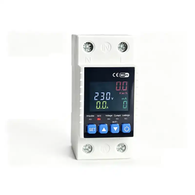
LMGQ7 Over Voltage Protection Circuit Breaker
LMGQ7 Over Voltage Protection Circuit Breaker
This DIN rail over voltage protection circuit breaker offers 3-in-1 overvoltage, undervoltage and overcurrent protection for single-phase AC220V circuits. It cuts off power automatically at abnormal voltage/current and resumes power with adjustable delay after fault fixed, with digital real-time V/A display for household & solar circuit safety.
This DIN rail over voltage protection circuit breaker offers 3-in-1 overvoltage, undervoltage and overcurrent protection for single-phase AC220V circuits. It cuts off power automatically at abnormal voltage/current and resumes power with adjustable delay after fault fixed, with digital real-time V/A display for household & solar circuit safety.
1. Product Overview
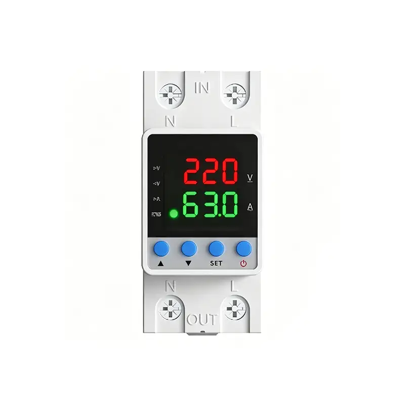
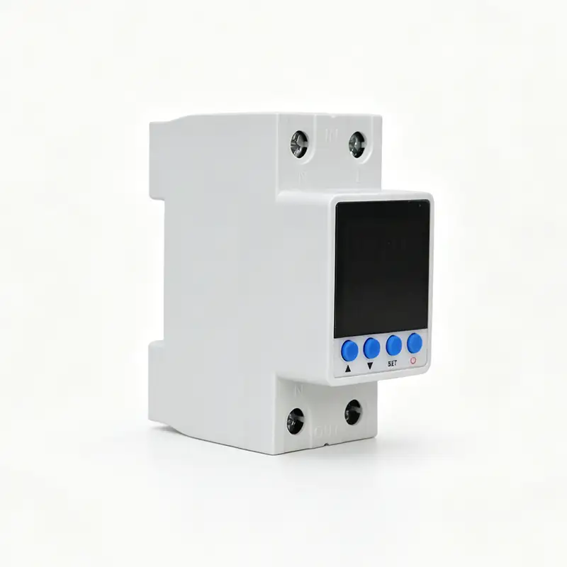
This is an intelligent DIN-rail mounted single-phase protector with dual LED digital display(Red for Voltage, Green for Current), integrating Overvoltage, Undervoltage, Overcurrent three protections + auto-reclosing function. It cuts off load automatically when voltage/current exceeds preset safe value; after circuit recovers to normal condition with delay time, it restores power supply automatically to protect household appliances, distribution equipment from burnout caused by abnormal grid voltage or overload current.
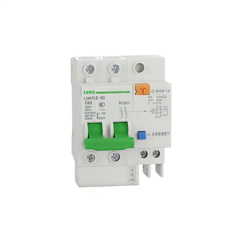
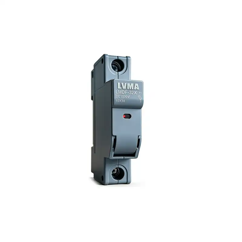
Applicable field: Residential distribution box, small commercial single-phase AC 50/60Hz 230V power system, rated optional specification: 16A/32A/40A/63A/80A.
2. Main Technical Specifications
| Item | Parameter |
|---|---|
| Rated Working Voltage | AC170~300V 50Hz |
| Overvoltage adjustable range | 230V ~ 290V (OFF=disable OV protection) |
| Undervoltage adjustable range | 140V ~ 210V (OFF=disable UV protection) |
| Overcurrent setting range | 1A ~ 63A (OFF=disable OC protection) |
| Auto-recovery delay | 5s ~ 999s adjustable |
| Power-on switch-on delay | 3s ~ 999s adjustable |
| Ambient working temp | -10℃ ~ +55℃ |
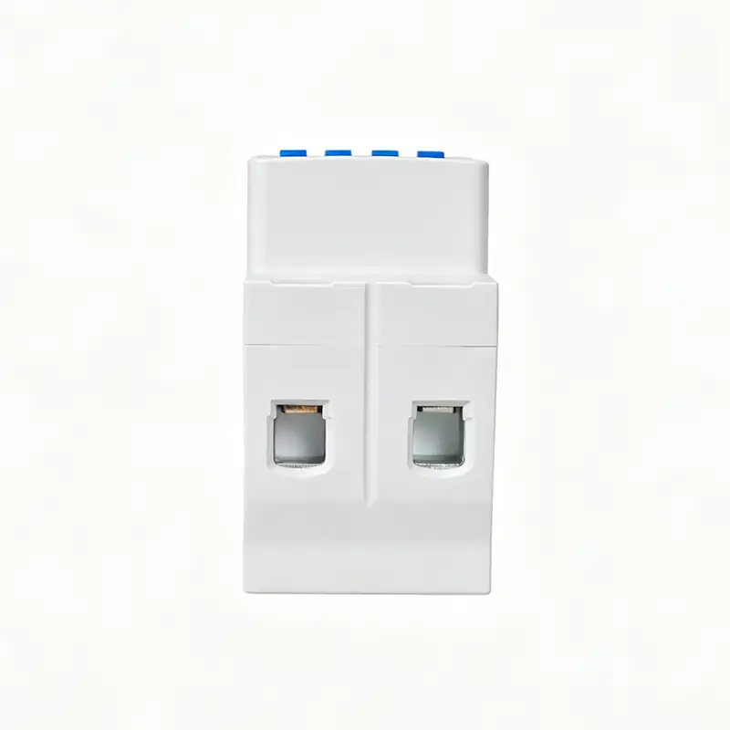
| Installation | Standard 35mm DIN rail |
3. Front Panel Definition
3.1 Button Definition (4 Buttons: ▲ UP / ▼ DOWN / SET / POWER)
- ▲ UP Key: Parameter value increase / switch display mode;
- ▼ DOWN Key: Parameter value decrease / switch display mode;
- SET Key: Enter parameter setting menu / confirm saved data;
- POWER Key (Red icon): Manual forced switch ON/OFF for emergency operation.
Green indicator light: Normal working status; Light off=protection tripped & power cut off.
4. Wiring Instruction
- Upper terminals marked IN: Connect incoming AC power source (L live wire, N neutral wire);
- Lower terminals marked OUT: Connect load side distribution circuit;
⚠️ Warning: Must follow L/N wiring definition, wrong wiring will cause device permanent damage.
5. Parameter Setting Steps
- Short press SET to enter setting menu, cyclic switch among 5 adjustable items:
P1: Overvoltage protection value | P2: Undervoltage protection value | P3: Overcurrent protection value | P4: Auto-restore delay time | P5: Factory data reset - After select target item via SET, use ▲ / ▼ to modify numerical value;
- Press SET again to save current parameter and jump to next setting item;
- Exit setting mode automatically if no button operation within 8s, return real-time V/A dual display.
Parameter Menu Table(P-1~P-12)
| Code | Function | Range | OFF Description |
|---|---|---|---|
| P-1 | Power-on Delay | 1~999s | – |
| P-2 | Auto-recovery Delay | 1~999s | – |
| P-3 | Overvoltage Set | 230~300V | OFF: Close OV protection |
| P-4 | Undervoltage Set | 140~210V | OFF: Close UV protection |
| P-5 | Reserved | – | – |
| P-6 | Overcurrent Set | 1~63A | OFF: Close OC protection |
| P-7 | Reserved | – | – |
| P-8 | Fault Counter | 0~20 times | Lock when over limit |
| P-9 | Reserved | – | – |
| P-10 | Display Mode | 1-Standard/2-Manual/3-Auto | – |
| P-11 | Screen-off Mode | ON/OFF | OFF=Always display; ON=Auto screen off |
| P-12 | Fault Clear(LOX) | 000~999 | Clear fault record |
6. Working Protection Principle
- Overvoltage Protection: When input voltage>set P1 value → device cuts output immediately; voltage drops back within normal range and waits preset delay → auto switch on output;
- Undervoltage Protection: When input voltage<set P2 value → trip cut-off; voltage recover up to normal threshold + delay → auto restore power;
- Overcurrent Protection: Load current>P3 setting → instant power off; reduce load current to rated scope + delay → auto close output;
- Manual control: Press red POWER button to manually force power ON/OFF regardless of protection state.
7. Safety Precautions
- Installation & maintenance must be operated by certified electrician, cut upstream power supply before wiring;
- Load total rated power cannot exceed the rated current of this protector;
- Install on vertical DIN rail, avoid damp, high-temperature, dusty environment;
- If device keeps repeated tripping frequently, check grid quality or load short-circuit fault before reset parameters.
8. Technical Documents & Support
Download the full datasheet for detailed specifications, wiring diagrams, and trip coordination guidelines.
Contact our engineering team for custom configurations, communication module integration, or OEM solutions for large-scale projects.
Request a quote with your project details for bulk pricing, lead times, and compliance certifications.
1. Product Overview
This is an intelligent DIN-rail mounted single-phase protector with dual LED digital display(Red for Voltage, Green for Current), integrating Overvoltage, Undervoltage, Overcurrent three protections + auto-reclosing function. It cuts off load automatically when voltage/current exceeds preset safe value; after circuit recovers to normal condition with delay time, it restores power supply automatically to protect household appliances, distribution equipment from burnout caused by abnormal grid voltage or overload current.
Applicable field: Residential distribution box, small commercial single-phase AC 50/60Hz 230V power system, rated optional specification: 16A/32A/40A/63A/80A.
2. Main Technical Specifications
| Item | Parameter |
|---|---|
| Rated Working Voltage | AC170~300V 50Hz |
| Overvoltage adjustable range | 230V ~ 290V (OFF=disable OV protection) |
| Undervoltage adjustable range | 140V ~ 210V (OFF=disable UV protection) |
| Overcurrent setting range | 1A ~ 63A (OFF=disable OC protection) |
| Auto-recovery delay | 5s ~ 999s adjustable |
| Power-on switch-on delay | 3s ~ 999s adjustable |
| Ambient working temp | -10℃ ~ +55℃ |
| Installation | Standard 35mm DIN rail |
3. Front Panel Definition
3.1 Button Definition (4 Buttons: ▲ UP / ▼ DOWN / SET / POWER)
- ▲ UP Key: Parameter value increase / switch display mode;
- ▼ DOWN Key: Parameter value decrease / switch display mode;
- SET Key: Enter parameter setting menu / confirm saved data;
- POWER Key (Red icon): Manual forced switch ON/OFF for emergency operation.
Green indicator light: Normal working status; Light off=protection tripped & power cut off.
4. Wiring Instruction
- Upper terminals marked IN: Connect incoming AC power source (L live wire, N neutral wire);
- Lower terminals marked OUT: Connect load side distribution circuit;
⚠️ Warning: Must follow L/N wiring definition, wrong wiring will cause device permanent damage.
5. Parameter Setting Steps
- Short press SET to enter setting menu, cyclic switch among 5 adjustable items:
P1: Overvoltage protection value | P2: Undervoltage protection value | P3: Overcurrent protection value | P4: Auto-restore delay time | P5: Factory data reset - After select target item via SET, use ▲ / ▼ to modify numerical value;
- Press SET again to save current parameter and jump to next setting item;
- Exit setting mode automatically if no button operation within 8s, return real-time V/A dual display.
Parameter Menu Table(P-1~P-12)
| Code | Function | Range | OFF Description |
|---|---|---|---|
| P-1 | Power-on Delay | 1~999s | – |
| P-2 | Auto-recovery Delay | 1~999s | – |
| P-3 | Overvoltage Set | 230~300V | OFF: Close OV protection |
| P-4 | Undervoltage Set | 140~210V | OFF: Close UV protection |
| P-5 | Reserved | – | – |
| P-6 | Overcurrent Set | 1~63A | OFF: Close OC protection |
| P-7 | Reserved | – | – |
| P-8 | Fault Counter | 0~20 times | Lock when over limit |
| P-9 | Reserved | – | – |
| P-10 | Display Mode | 1-Standard/2-Manual/3-Auto | – |
| P-11 | Screen-off Mode | ON/OFF | OFF=Always display; ON=Auto screen off |
| P-12 | Fault Clear(LOX) | 000~999 | Clear fault record |
6. Working Protection Principle
- Overvoltage Protection: When input voltage>set P1 value → device cuts output immediately; voltage drops back within normal range and waits preset delay → auto switch on output;
- Undervoltage Protection: When input voltage<set P2 value → trip cut-off; voltage recover up to normal threshold + delay → auto restore power;
- Overcurrent Protection: Load current>P3 setting → instant power off; reduce load current to rated scope + delay → auto close output;
- Manual control: Press red POWER button to manually force power ON/OFF regardless of protection state.
7. Safety Precautions
- Installation & maintenance must be operated by certified electrician, cut upstream power supply before wiring;
- Load total rated power cannot exceed the rated current of this protector;
- Install on vertical DIN rail, avoid damp, high-temperature, dusty environment;
- If device keeps repeated tripping frequently, check grid quality or load short-circuit fault before reset parameters.
8. Technical Documents & Support
Download the full datasheet for detailed specifications, wiring diagrams, and trip coordination guidelines.
Contact our engineering team for custom configurations, communication module integration, or OEM solutions for large-scale projects.
Request a quote with your project details for bulk pricing, lead times, and compliance certifications.

Related Products
Contact Us
Have questions about our products or services? Our team is here to help you with any inquiries.